REAR DOOR SUNSHADE SYSTEM Front and Rear Switch cannot Operate Right Door Sunshade
DESCRIPTION
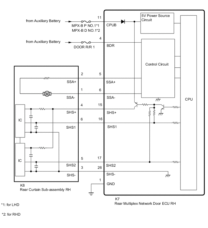
The left rear door sunshade is controlled by the rear multiplex network door ECU RH and operates the rear curtain sub-assembly RH.
WIRING DIAGRAM
CAUTION / NOTICE / HINT
Note
Inspect fuses for circuits related to this system before performing the following inspection procedure.
PROCEDURE
-
PERFORM ACTIVE TEST USING GTS
-
Using the GTS, perform the Active Test.
Body Electrical > Rear Right Door > Active TestTester Display Measurement Item Control Range Diagnostic Note Rear Door Sunshade Up Rear curtain sub-assembly RH close operation Up or Stop w/ Side Window Curtain specification: a rear side window curtain assembly RH close operation is also performed Rear Door Sunshade Down Rear curtain sub-assembly RH open operation Down or Stop w/ Side Window Curtain specification: a rear side window curtain assembly RH open operation is also performed
Body Electrical > Rear Right Door > Active TestTester Display Rear Door Sunshade Up
Body Electrical > Rear Right Door > Active TestTester Display Rear Door Sunshade Down OK The Active Test is performed normally. Result Proceed to OK NG
NG 
CHECK HARNESS AND CONNECTOR (REAR MULTIPLEX NETWORK DOOR ECU RH - BATTERY AND BODY GROUND) Click here
OK 
-
-
CHECK HARNESS AND CONNECTOR (REAR MULTIPLEX NETWORK DOOR ECU RH - REAR CURTAIN SUB-ASSEMBLY RH)
-
Disconnect the K7 rear multiplex network door ECU RH connector.
-
Disconnect the K8 rear curtain sub-assembly RH connector.
-
Measure the resistance according to the value(s) in the table below.
Standard Resistance Tester Connection Condition Specified Condition K7-15 (SHS+) - K8-4 (SHS+) Always Below 1 Ω K7-16 (SHS1) - K8-6 (SHS1) Always Below 1 Ω K7-17 (SHS2) - K8-5 (SHS2) Always Below 1 Ω K7-26 (SHS-) - K8-3 (SHS-) Always Below 1 Ω K7-15 (SHS+) or K8-4 (SHS+) - Body ground Always 10 kΩ or higher K7-16 (SHS1) or K8-6 (SHS1) - Body ground Always 10 kΩ or higher K7-17 (SHS2) or K8-5 (SHS2) - Body ground Always 10 kΩ or higher K7-26 (SHS-) or K8-3 (SHS-) - Body ground Always 10 kΩ or higher Result Proceed to OK NG
NG 
REPAIR OR REPLACE HARNESS OR CONNECTOR
OK
-
-
CHECK REAR MULTIPLEX NETWORK DOOR ECU RH
-
Disconnect the K8 rear curtain sub-assembly RH connector.
-
Measure the resistance according to the value(s) in the table below.
Standard Resistance Tester Connection Condition Specified Condition K8-3 (SHS-) - Body ground Always Below 1 Ω -
Measure the voltage according to the value(s) in the table below.
Standard Voltage Tester Connection Switch Condition Specified Condition K8-4 (SHS+) -Body ground Power switch on (IG) 11 to 14 V K8-5 (SHS2) - Body ground Power switch on (IG) 11 to 14 V K8-6 (SHS1) - Body ground Power switch on (IG) 11 to 14 V Result Proceed to OK NG
OK
REPLACE REAR CURTAIN SUB-ASSEMBLY RH Click here
NG
REPLACE REAR MULTIPLEX NETWORK DOOR ECU RH Click here
-
-
CHECK HARNESS AND CONNECTOR (REAR MULTIPLEX NETWORK DOOR ECU RH - BATTERY AND BODY GROUND)
-
Disconnect the K7 rear multiplex network door ECU RH connector.
-
Measure the resistance according to the value(s) in the table below.
Standard Resistance Tester Connection Condition Specified Condition K7-1 (GND) - Body ground Always Below 1 Ω -
Measure the voltage according to the value(s) in the table below.
Standard Voltage Tester Connection Switch Condition Specified Condition K7-4 (BDR) - Body ground Power switch off 11 to 14 V K7-11 (CPUB) - Body ground Power switch off 11 to 14 V Result Proceed to OK NG
NG
REPAIR OR REPLACE HARNESS OR CONNECTOR
OK
-
-
INSPECT REAR CURTAIN SUB-ASSEMBLY RH
-
Remove the rear curtain sub-assembly RH.
-
Inspect the rear curtain sub-assembly RH.
Result Proceed to OK NG
NG
REPLACE REAR CURTAIN SUB-ASSEMBLY RH Click here
OK
-
-
CHECK HARNESS AND CONNECTOR (REAR MULTIPLEX NETWORK DOOR ECU RH - REAR CURTAIN SUB-ASSEMBLY RH)
-
Disconnect the K7 rear multiplex network door ECU RH connector.
-
Disconnect the K8 rear curtain sub-assembly RH connector.
-
Measure the resistance according to the value(s) in the table below.
Standard Resistance Tester Connection Condition Specified Condition K7-5 (SSA+) - K8-2 (SSA+) Always Below 1 Ω K7-6 (SSA-) - K8-1 (SSA-) Always Below 1 Ω K7-5 (SSA+) or K8-2 (SSA+) - Body ground Always 10 kΩ or higher K7-6 (SSA-) or K8-1 (SSA-) - Body ground Always 10 kΩ or higher Result Proceed to OK NG
OK
REPLACE REAR MULTIPLEX NETWORK DOOR ECU RH Click here
NG
REPAIR OR REPLACE HARNESS OR CONNECTOR
-