POWER POINT SOCKET(for Instrument Panel Side) INSTALLATION
CAUTION / NOTICE / HINT
Tech Tips
-
Use the same procedure for RHD and LHD vehicles.
-
The procedure listed below is for LHD vehicles.
PROCEDURE
-
INSTALL NO. 2 POWER OUTLET SOCKET COVER
-

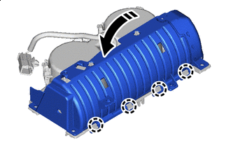
Install in this Direction Attach the claw and install the No. 2 power outlet socket cover to the console panel as shown in the illustration.
-
-
INSTALL NO. 1 POWER OUTLET SOCKET ASSEMBLY
-
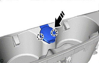
Install in this Direction Attach the claw and install the No. 1 power outlet socket assembly as shown in the illustration.
Note
-
Do not subject the No. 1 power outlet socket assembly to any strong impact (such as dropping).
-
If the No. 1 power outlet socket assembly is subjected to any strong impact, replace the No. 1 power outlet socket assembly with a new one.
-
-
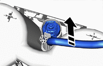
Install in this Direction Install the connector to install the wire harness clamp as shown in the illustration.
-
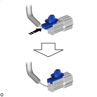
Install in this Direction Attach the claw in direction indicated by the arrow shown in the illustration.
-
for LHD:
-
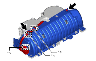
*a Hook *b Clamp Install the 2 screws.
-
Attach the hook and clamp.
-
-
for RHD:
-
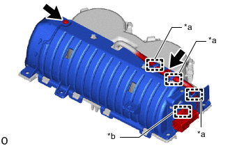
*a Hook *b Clamp Install the 2 screws.
-
Attach the hook and clamp.
-
-
-
INSTALL INSTRUMENT PANEL CUP HOLDER SUB-ASSEMBLY
-
INSTALL INTEGRATION CONTROL AND PANEL ASSEMBLY
-
INSTALL REMOTE OPERATION CONTROLLER ASSEMBLY
-
INSTALL UPPER CONSOLE PANEL ASSEMBLY
-
INSTALL SHIFT LEVER KNOB SUB-ASSEMBLY