CAUTION / NOTICE / HINT
-
Use the same procedure for RHD and LHD vehicles.
-
The procedure listed below is for LHD vehicles.
PROCEDURE
- Click here
REMOVE SHIFT LEVER KNOB SUB-ASSEMBLY
- Click here
REMOVE UPPER CONSOLE PANEL ASSEMBLY
- Click here
REMOVE REMOTE OPERATION CONTROLLER ASSEMBLY
- Click here
REMOVE INTEGRATION CONTROL AND PANEL ASSEMBLY
- Click here
REMOVE INSTRUMENT PANEL CUP HOLDER SUB-ASSEMBLY
- Click here
REMOVE NO. 1 POWER OUTLET SOCKET ASSEMBLY
-
for LHD:
-
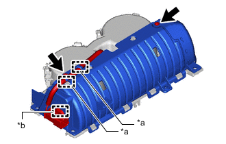
*a Hook *b Clamp Remove the 2 screws.
-
Detach the hook and clamp.
-
-
for RHD:
-
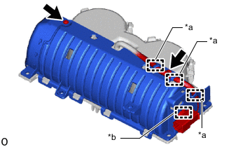
*a Hook *b Clamp Remove the 2 screws.
-
Detach the hook and clamp.
-
-
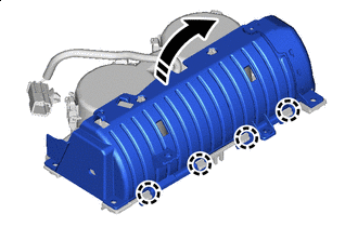

Remove in this Direction Detach the claw and remove the cover as shown in the illustration.
Note:Do not completely remove the cover. Make sure that the cloth and cover are connected.
Note: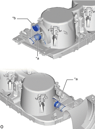
*a Spring *b Damper Do not touch the spring and damper. Otherwise, the operation of the instrument panel cup holder sub-assembly may be affected.
-
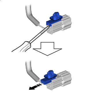
Remove in this Direction 
Protective tape Using a thin-bladed screwdriver with its tip wrapped with protective tape, remove the connector to remove the wire harness clamp as shown in the illustration.
-
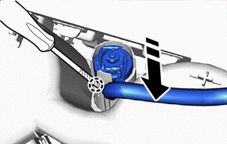
Remove in this Direction Protective tape Using a thin-bladed screwdriver with its tip wrapped with protective tape, detach the claw and remove the No. 1 power outlet socket assembly as shown in the illustration.
Note:
-
Do not subject the No. 1 power outlet socket assembly to any strong impact (such as dropping).
-
If the No. 1 power outlet socket assembly is subjected to any strong impact, replace the No. 1 power outlet socket assembly with a new one.
-
-
- Click here
REMOVE NO. 2 POWER OUTLET SOCKET COVER
-
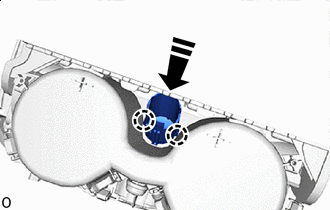
Remove in this Direction Detach the claw and remove the No. 2 power outlet socket cover as shown in the illustration.
-