COMPRESSOR(for AWD) INSTALLATION
PROCEDURE
-
ADJUST COMPRESSOR OIL
-
When replacing the compressor with motor assembly with a new one, gradually discharge the inert gas from the service valve, and drain the following amount of oil from the new compressor with motor assembly before installation.
Standard 30 cc (1.01 fl.oz) from new compressor with motor assembly. Note
-
If a new compressor with motor assembly is installed without removing some oil, there will be too much oil in the system due to the oil remaining in the pipes of the vehicle. Excessive oil in the system prevents heat exchange in the refrigeration cycle and causes ineffective cooling.
-
If the amount of oil remaining in the old compressor with motor assembly is too small, check the air conditioning system for oil leaks.
-
Be sure to use ND-OIL 11 or equivalent compressor oil. If any compressor oil other than ND-OIL 11 is used, compressor with motor assembly insulation performance may decrease, resulting in leakage of electric power.
-
-
-
INSTALL COMPRESSOR WITH MOTOR ASSEMBLY
-
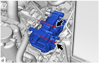
Using an E8 "TORX" socket wrench, temporarily install the compressor with motor assembly with the 2 stud bolts.
- Torque:
- 10 N*m { 102 kgf*cm, 7 ft.*lbf }
-

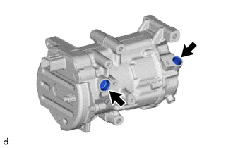
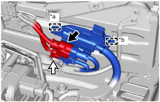
Nut 
Bolt Install the compressor with motor assembly with the 2 nuts and 2 bolts.
Note
Tighten the 2 nuts and 2 bolts in the order shown in the illustration.
- Torque:
- 24.5 N*m { 250 kgf*cm, 18 ft.*lbf }
-
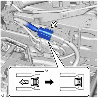
Remove the vinyl tape wrapped around the connector (E).
-
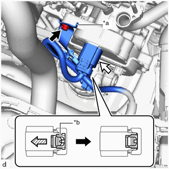
*a Stopper *b Green-colored Lock Bolt (B) Connector (E) 
Slide Connect the connector (E) and slide the green-colored lock as shown in the illustration to lock it securely.
CAUTION:
Make sure to wear insulating gloves.
Note
Make sure that the connector is connected securely.
-
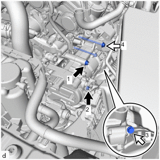
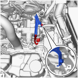
Install the wiring harness clamp bracket (bolt (B) fastening side) with the bolt (B).
Note
Install with a stopper on upper area of the compressor with motor assembly.
- Torque:
- 10 N*m { 102 kgf*cm, 7 ft.*lbf }
-
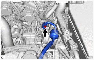
*a Rib Bolt (A) Connector (D) Install the wiring harness clamp bracket (bolt (A) fastening side) with the bolt (A).
Note
Install by attaching the rib on the surface of the compressor with motor assembly as shown in the illustration.
- Torque:
- 10 N*m { 102 kgf*cm, 7 ft.*lbf }
-
Connect the connector (D).
-
-
INSTALL NO. 13 CONNECTOR HOLDER
-
*a Clamp *b Guide Connector (B) Connector (C) Attach the clamp and guide to install the No. 13 connector holder.
-
Connect the connector (B) and connector (C).
-
Remove the vinyl tape wrapped around the connector (A).
-
*a Green-colored Lock Connector (A) Slide Connect the connector (A) and slide the green-colored lock as shown in the illustration to lock it securely.
CAUTION:
Make sure to wear insulating gloves.
Note
Make sure that the connector is connected securely.
-
-
CONNECT DISCHARGE HOSE SUB-ASSEMBLY
-
Remove the vinyl tape from the discharge hose sub-assembly and connecting part of the compressor with motor assembly.
-
Sufficiently apply compressor oil to a new O-ring and the fitting surface of the compressor with motor assembly.
Compressor Oil ND-OIL 11 or equivalent Note
Do not use any compressor oil other than ND-OIL 11 or equivalent. If any compressor oil other than ND-OIL 11 or equivalent is used, compressor motor insulation performance may decrease, resulting in leakage of electric power.
-
Install the O-ring to the discharge hose sub-assembly.
Note
Keep the O-ring and O-ring fitting surface free of foreign matter.
-
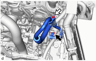
Connect the discharge hose sub-assembly to the compressor with motor assembly with the bolt.
- Torque:
- 9.8 N*m { 100 kgf*cm, 87 in.*lbf }
Note
-
Do not apply excessive force to the discharge hose sub-assembly.
-
Make sure not to cut the O-ring while installing it. (Cut O-rings cannot be installed)
-
-
INSTALL SUCTION HOSE SUB-ASSEMBLY
-
Remove the vinyl tape from the suction hose sub-assembly, suction tube sub-assembly B and connecting part of the compressor with motor assembly.
-
Sufficiently apply compressor oil to 2 new O-rings and the fitting surface of the suction tube sub-assembly B and the fitting surface of the compressor with motor assembly.
Compressor Oil ND-OIL 11 or equivalent Note
Do not use any compressor oil other than ND-OIL 11 or equivalent. If any compressor oil other than ND-OIL 11 or equivalent is used, compressor motor insulation performance may decrease, resulting in leakage of electric power.
-
Install the 2 O-rings to the suction hose sub-assembly.
Note
Keep the O-ring and O-ring fitting surface free of foreign matter.
-
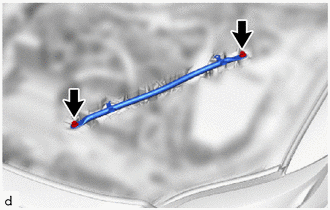
Bolt Nut Install the suction hose sub-assembly to the compressor with motor assembly with the bolt and nut.
- Torque:
- 9.8 N*m { 100 kgf*cm, 87 in.*lbf }
Note
-
Do not apply excessive force to the suction hose sub-assembly.
-
Make sure not to cut the O-ring while installing it. (Cut O-rings cannot be installed)
-
-
INSTALL ECM
-
INSTALL RADIATOR SUPPORT TO CROSSMEMBER BRACE SUB-ASSEMBLY LH
-
Install the radiator support to crossmember brace sub-assembly LH with the 2 bolts.
- Torque:
- 49 N*m { 500 kgf*cm, 36 ft.*lbf }
-
-
INSTALL SERVICE PLUG GRIP
-
CHARGE AIR CONDITIONING SYSTEM WITH REFRIGERANT
-
for HFC-134a(R134a):
-
for HFO-1234yf(R1234yf):
-
-
WARM UP COMPRESSOR
-
for HFC-134a(R134a):
-
for HFO-1234yf(R1234yf):
-
-
INSPECT FOR REFRIGERANT LEAK
-
for HFC-134a(R134a):
-
for HFO-1234yf(R1234yf):
-
-
INSTALL LOWER RADIATOR AIR DEFLECTOR
-
INSTALL UPPER RADIATOR SUPPORT SEAL
-
INSTALL RADIATOR COVER PLATE
-
INSTALL V-BANK COVER SUB-ASSEMBLY