CAUTION / NOTICE / HINT
The necessary procedures (adjustment, calibration, initialization, or registration) that must be performed after parts are removed, installed, or replaced during the compressor with motor assembly removal/installation are shown below.
| Replaced Part or Performed Procedure | Necessary procedures | Effect/Inoperative Function when Necessary Procedure not Performed | Link |
|---|---|---|---|
| Disconnect cable from negative (-) auxiliary battery terminal | Memorize steering angle neutral point | LKA/LDA system (for Mono camera type) | for Stereo Camera type:Click here for Mono Camera type:Click here |
| Lane control system (for Stereo camera type) | |||
| Parking support brake system* | |||
| Pre-collision system (for Stereo camera type) | |||
| Pre-collision system (for Mono camera type) | |||
| Adaptive high beam system | |||
|
|||
| Variable gear ratio steering system | |||
| Parking assist monitor system | |||
| Panoramic view monitor system | |||
| Initialize rear door sunshade system | Rear door sunshade system | ||
| Initialize power trunk lid system | Power trunk lid system |
-
This vehicle has contains high voltage circuits standardized with orange colored wiring and connectors, so follow the instructions in this manual to perform the procedures correctly.
-
If the correct procedures are not followed according to the instructions in this manual, there is a danger of electric shock from the high voltage circuits.
-

Be sure to wear insulating gloves when working on high voltage wiring or components.
-
If work is performed without wearing insulating gloves, there is a danger of electric shock.
-
Use the same procedure for RHD and LHD vehicles.
-
The procedure listed below is for LHD vehicles.
PROCEDURE
- Click here
REMOVE V-BANK COVER SUB-ASSEMBLY
- Click here
REMOVE RADIATOR COVER PLATE
- Click here
REMOVE UPPER RADIATOR SUPPORT SEAL
- Click here
REMOVE LOWER RADIATOR AIR DEFLECTOR
- Click here
RECOVER REFRIGERANT FROM REFRIGERATION SYSTEM
-
for HFC-134a(R134a):
-
for HFO-1234yf(R1234yf):
-
- Click here
REMOVE SERVICE PLUG GRIP
- Click here
CHECK TERMINAL VOLTAGE
-
Remove the connector cover assembly.
-
Check the terminal voltage.
-
Install the connector cover assembly.
-
- Click here
REMOVE RADIATOR SUPPORT TO CROSSMEMBER BRACE SUB-ASSEMBLY LH
-
Remove the 2 bolts and radiator support to crossmember brace sub-assembly LH.
-
- Click here
REMOVE ECM
- Click here
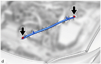
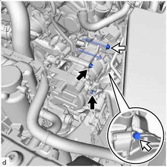
REMOVE SUCTION HOSE SUB-ASSEMBLY
-

Bolt 
Nut Remove the bolt, nut and suction hose sub-assembly from the compressor with motor assembly.
Note:Do not apply excessive force to the suction hose sub-assembly.
-
Remove the 2 O-rings from the suction hose sub-assembly.
Note:Seal the openings of the disconnected parts using vinyl tape to prevent moisture and foreign matter from entering them.
-
- Click here
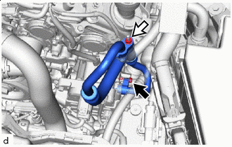
DISCONNECT DISCHARGE HOSE SUB-ASSEMBLY
-
Remove the bolt and disconnect the discharge hose sub-assembly from the compressor with motor assembly.
Note:Do not apply excessive force to the discharge hose sub-assembly.
-
Remove the O-ring from the discharge hose sub-assembly.
Note:Seal the openings of the disconnected parts using vinyl tape to prevent moisture and foreign matter from entering them.
-
- Click here
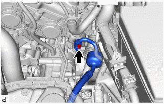
REMOVE NO. 13 CONNECTOR HOLDER
-
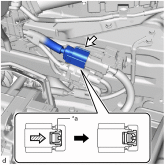
*a Green-colored Lock Connector (A) 
Slide Slide the green-colored lock of the connector (A) as shown in the illustration to release it and disconnect the connector.
CAUTION:Make sure to wear insulating gloves.
Note:Insulate the disconnected terminals and connector with vinyl tape.
-
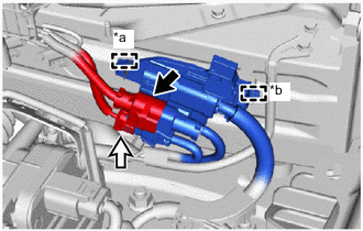
*a Clamp *b Guide Connector (B) Connector (C) Disconnect the connector (B) and connector (C).
-
Detach the clamp and guide and remove the No. 13 connector holder.
-
- Click here
REMOVE COMPRESSOR WITH MOTOR ASSEMBLY
-
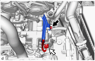
Bolt (A) Connector (D) Disconnect the connector (D).
-
Remove the bolt (A) and disconnect the wiring harness clamp bracket (bolt (A) fastening side).
-
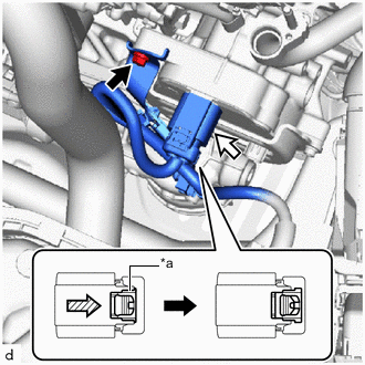
*a Green-colored Lock Bolt (B) Connector (E) Slide Remove the bolt (B) and disconnect the wiring harness clamp bracket (bolt (B) fastening side).
-
Slide the green-colored lock of the connector (E) as shown in the illustration to release it and disconnect the connector.
CAUTION:Make sure to wear insulating gloves.
Note:Insulate the disconnected terminals and connector with vinyl tape.
-
Nut Bolt Remove the 2 nuts and 2 bolts.
-
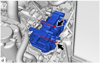
Using an E8 "TORX" socket wrench, remove the 2 stud bolts and compressor with motor assembly.
Note:Do not drop or subject the parts to any impact.
-