FRONT AIR CONDITIONING UNIT REASSEMBLY
CAUTION / NOTICE / HINT
Tech Tips
-
Use the same procedure for RHD and LHD vehicles.
-
The procedure listed below is for LHD vehicles.
PROCEDURE
-
INSTALL NO. 4 COOLING UNIT PACKING
-
Install a new No. 4 cooling unit packing in the position shown in the illustration.
Note
Check that any remaining No. 4 cooling unit packing has been completely removed from the heater case.
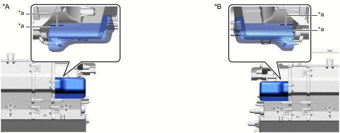
*A for LHD *B for RHD *a Specified Application Position for Packing - -
-
-
INSTALL NO. 2 COOLING UNIT BRACKET
-
*A for LHD *B for RHD Attach the guide.
-
Install the No. 2 cooling unit bracket with the screw.
-
-
INSTALL NO. 1 COOLING UNIT BRACKET
-
*A for LHD *B for RHD Attach the guide.
-
Install the No. 1 cooling unit bracket with the screw.
-
-
INSTALL NO. 1 COOLER THERMISTOR
-
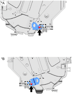
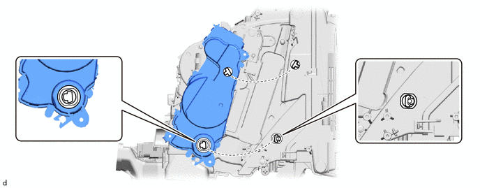
INSTALL NO. 1 COOLER EVAPORATOR SUB-ASSEMBLY
-
Install the No. 1 cooler evaporator sub-assembly to the heater case as shown in the illustration.
-
for LHD:
-
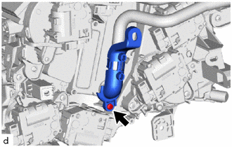
While inserting the No. 1 cooler thermistor into the guide, insert the guide pin and attach the claw as shown in the illustration.
*a Clamp *b Guide *c Guide Pin *d No. 1 Cooler Thermistor Lead Wire 
Secure the lead wire between the guide - - -
Install the heater case with the 2 screws.
-
Attach the clamp.
-
-
for RHD:
-
While inserting the No. 1 cooler thermistor into the guide, insert the guide pin and attach the claw as shown in the illustration.
*a Clamp *b Guide *c Guide Pin *d No. 1 Cooler Thermistor Lead Wire Secure the lead wire between the guide - - -
Install the heater case with the 2 screws.
-
Attach the clamp.
-
-
-
INSTALL HEATER AIR DAMPER ASSEMBLY
-
Attach the claw and guide pin.
-
Install the heater air damper assembly with the screw.
-
-
-
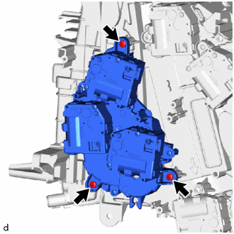
INSTALL NO. 5 AIR CONDITIONING RADIATOR DAMPER SERVO SUB-ASSEMBLY (for RHD)
-
Align the direction of the fitting on the heater case to the fitting on the No. 5 air conditioning radiator damper servo sub-assembly as shown in the illustration.
-
Install the No. 5 air conditioning radiator damper servo sub-assembly with the 3 screws.
-
-
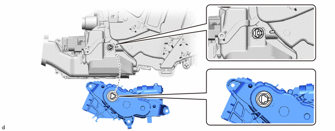
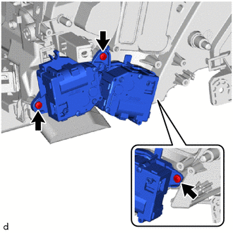
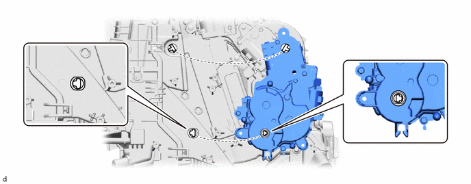
INSTALL NO. 3 AIR CONDITIONING RADIATOR DAMPER SERVO SUB-ASSEMBLY (for LHD)
-
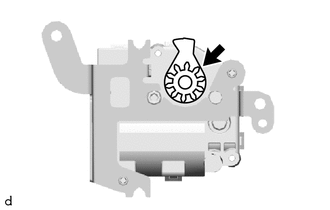
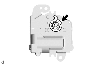
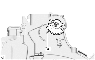
Remove the gear of the No. 3 air conditioning radiator damper servo sub-assembly.
-
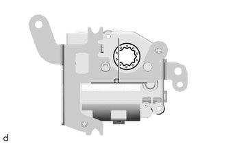
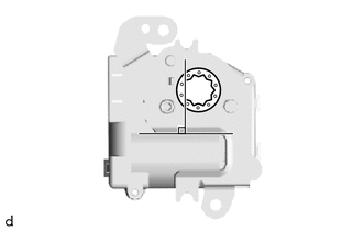
Align the No. 3 air conditioning radiator damper servo sub-assembly with the standard position and install the gear.
-
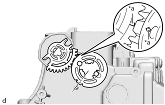
*a Matchmarks Align with the matchmarks on the gear as shown in the illustration.
-
Align the guide and install the No. 3 air conditioning radiator damper servo sub-assembly with the 2 screws.
-
-
INSTALL NO. 6 AIR CONDITIONING RADIATOR DAMPER SERVO SUB-ASSEMBLY (for LHD)
-
Align the direction of the fitting on the heater case to the fitting on the No. 6 air conditioning radiator damper servo sub-assembly as shown in the illustration.

-
Install the No. 6 air conditioning radiator damper servo sub-assembly with the 3 screws.
-
-
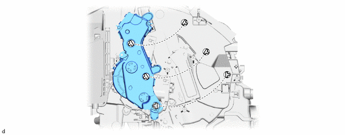
INSTALL NO. 1 AIR CONDITIONING RADIATOR DAMPER SERVO SUB-ASSEMBLY (for RHD)
-
Align the direction of the fitting on the heater case to the fitting on the No. 1 air conditioning radiator damper servo sub-assembly as shown in the illustration.
-
Install the No. 1 air conditioning radiator damper servo sub-assembly with the 3 screws.
-
-
INSTALL NO. 4 AIR CONDITIONING RADIATOR DAMPER SERVO SUB-ASSEMBLY
-
Align the direction of the fitting on the heater case to the fitting on the No. 4 air conditioning radiator damper servo sub-assembly as shown in the illustration.
-
Install the No. 4 air conditioning radiator damper servo sub-assembly with the 3 screws.
-
-
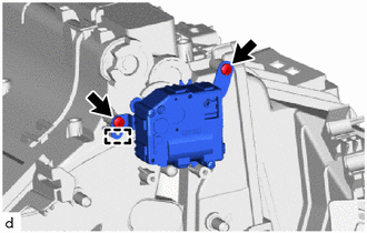
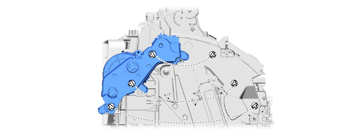
INSTALL NO. 5 AIR CONDITIONING RADIATOR DAMPER SERVO SUB-ASSEMBLY (for LHD)
-
Align the direction of the fitting on the heater case to the fitting on the No. 5 air conditioning radiator damper servo sub-assembly as shown in the illustration.
-
Install the No. 5 air conditioning radiator damper servo sub-assembly with the 3 screws.
-
-
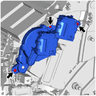
INSTALL NO. 1 AIR CONDITIONING RADIATOR DAMPER SERVO SUB-ASSEMBLY (for LHD)
-
Align the direction of the fitting on the heater case to the fitting on the No. 1 air conditioning radiator damper servo sub-assembly as shown in the illustration.
-
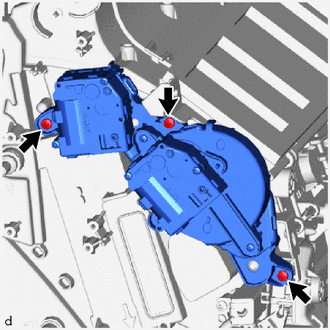
Install the No. 1 air conditioning radiator damper servo sub-assembly with the 3 screws.
-
-
INSTALL NO. 6 AIR CONDITIONING RADIATOR DAMPER SERVO SUB-ASSEMBLY (for RHD)
-
Align the direction of the fitting on the heater case to the fitting on the No. 6 air conditioning radiator damper servo sub-assembly as shown in the illustration.
-
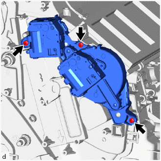
Install the No. 6 air conditioning radiator damper servo sub-assembly with the 3 screws.
-
-
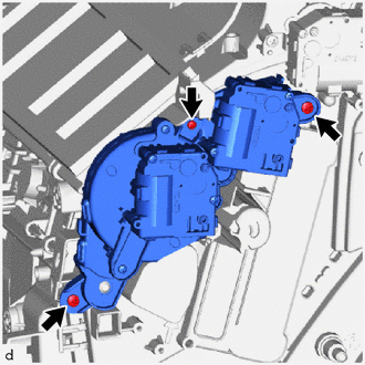
INSTALL NO. 2 AIR CONDITIONING RADIATOR DAMPER SERVO SUB-ASSEMBLY
-
Align the direction of the fitting on the heater case to the fitting on the No. 2 air conditioning radiator damper servo sub-assembly as shown in the illustration.
-
Install the No. 2 air conditioning radiator damper servo sub-assembly with the 3 screws.
-
-
INSTALL NO. 3 AIR CONDITIONING RADIATOR DAMPER SERVO SUB-ASSEMBLY (for RHD)
-
Remove the gear of the No. 3 air conditioning radiator damper servo sub-assembly.
-
Align the No. 3 air conditioning radiator damper servo sub-assembly with the standard position and install the gear.
-
*a Pin Align the gear with the position of the pin as shown in the illustration.
-
Align the guide and install the No. 3 air conditioning radiator damper servo sub-assembly with the 2 screws.
-
-
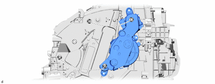
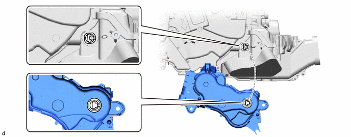
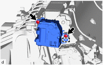
INSTALL NO. 3 COOLING UNIT BRACKET (for LHD)
-
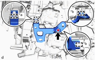
*a Guide *b Guide pin Attach the guide pin, guide and claw.
-
Install the No. 3 cooling unit bracket with the screw.
-
-
INSTALL NO. 1 COOLER COVER
-
Remove the vinyl tape from the cooler expansion valve.
-
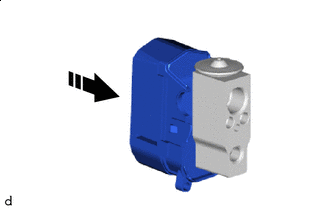
Install in this Direction Install the No. 1 cooler cover to the cooler expansion valve.
-
-
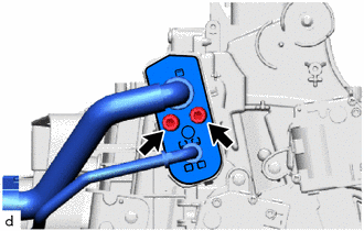
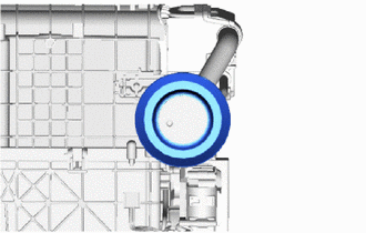
INSTALL COOLER EXPANSION VALVE
-
Remove the vinyl tape from the No. 1 cooler evaporator sub-assembly.
-
Apply sufficient compressor oil to 2 new O-rings and the fitting surface with the No. 1 cooler evaporator of the cooler expansion valve.
Compressor Oil ND-OIL 11 or equivalent -
Install the 2 O-rings to the No. 1 cooler evaporator sub-assembly.
Note
Keep the O-rings and O-ring fitting surfaces free of foreign matter.
-
Install the cooler expansion valve together with the No. 1 cooler cover.
Note
Make sure not to cut the O-ring while installing it. (Cut O-rings cannot be installed)
-
-
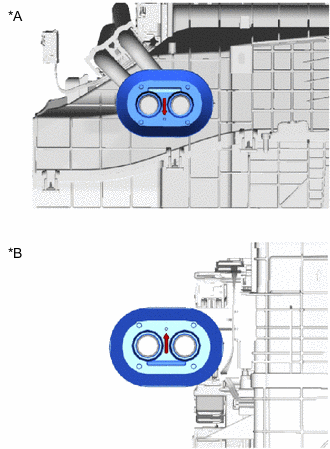
INSTALL AIR CONDITIONING TUBE ASSEMBLY
-
Remove the vinyl tape from the air conditioning tube assembly.
-
Apply a sufficient amount of compressor oil to 2 new O-rings and the fitting surface of the cooler expansion valve and air conditioning tube assembly.
Compressor Oil ND-OIL 11 or equivalent Note
Do not use any compressor oil other than ND-OIL 11 or equivalent. If any compressor oil other than ND-OIL 11 or equivalent is used, compressor motor insulation performance may decrease, resulting in leakage of electric power.
-
Install the 2 O-rings to the air conditioning tube assembly.
Note
Keep the O-rings and O-ring fitting surfaces free of foreign matter.
-
Using a 4 mm hexagon socket wrench, install the air conditioning accessory assembly with the 2 hexagon bolts.
- Torque:
- 3.5 N*m { 36 kgf*cm, 31 in.*lbf }
Note
Make sure not to cut the O-ring while installing it. (Cut O-rings cannot be installed)
-
-
INSTALL NO. 2 COOLER COVER
-
Attach the guide pin and claw to install the No. 2 cooler cover.
-
-
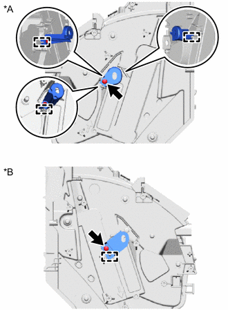
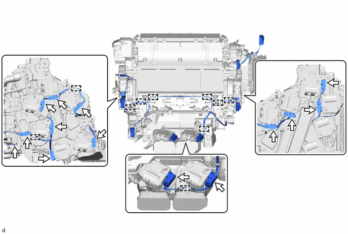
INSTALL AIR CONDITIONING HARNESS ASSEMBLY
-
for LHD:
-
Install the air conditioning harness assembly to the guide.
-
-
for RHD:
-
Install the air conditioning harness assembly to the guide.
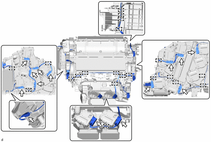
-
-
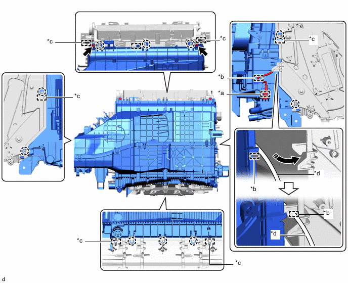
Attach the 14 connectors.
-
-
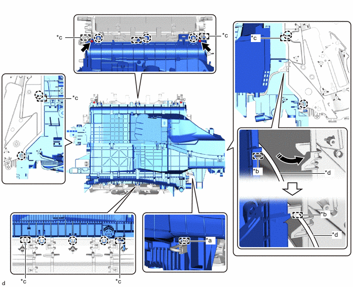
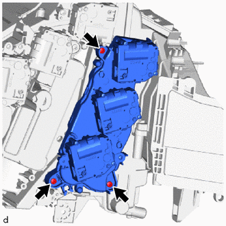
INSTALL PACKING
-
Install a new packing as shown in the illustration.
Note
Make sure that any remaining packing is completely removed from the air conditioner harness assembly and heater air damper assembly when removing.
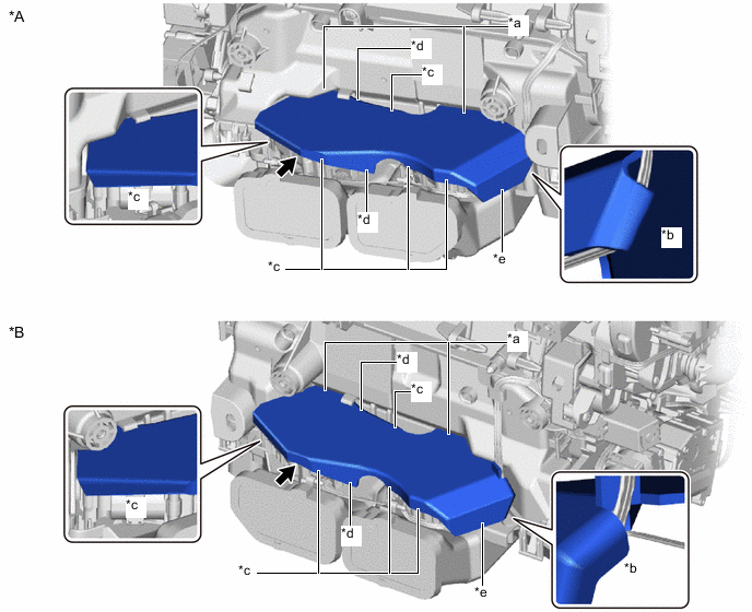
*A for LHD *B for RHD *a Apply packing so that it contacts the heater air damper assembly *b Apply packing so that it wraps around to the rear side of the air conditioner harness assembly *c Fold the packing into the inner side (Packing float is acceptable) *d Apply packing to the heater air damper assembly servo motor or to the side of the connector of the air conditioner harness assembly (Packing float is acceptable) *e Apply packing to the rear side of the air conditioner harness assembly connector - -
-
-
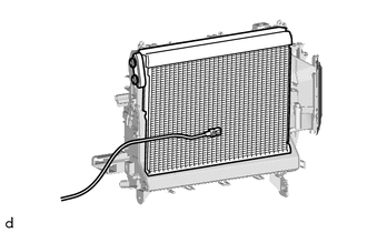
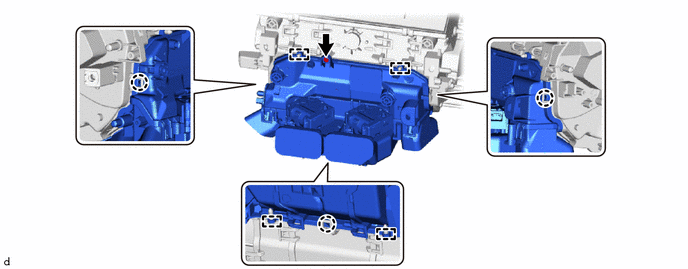
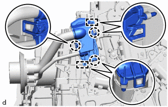
INSTALL HEATER RADIATOR UNIT SUB-ASSEMBLY
-
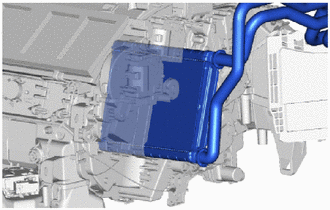
Insert the heater radiator unit sub-assembly into the heater case.
Note
Securely insert the heater radiator unit sub-assembly as far as it will go.
-
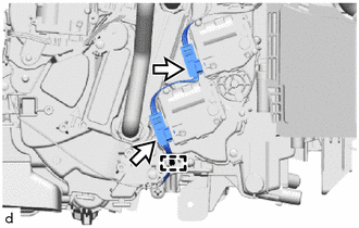
Attach the 2 connectors.
-
Attach the guide.
-
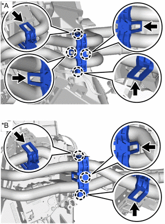
*A for LHD *B for RHD Attach the claw to install the heater clamp.
-
-
INSTALL NO. 3 COOLING UNIT BRACKET (for RHD)
-
Install the No. 3 cooling unit bracket with the screw.
-
-
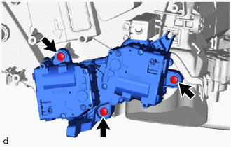
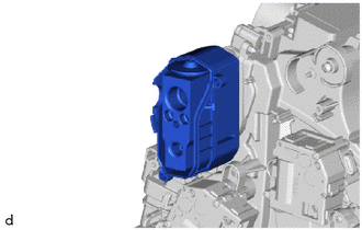
INSTALL QUICK HEATER ASSEMBLY (w/ PTC Heater)
-
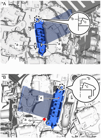
*A for LHD *B for RHD *a Matchmarks *b Heater Case Fitting Surface *c Quick Heater Claw Align the matchmark on the quick heater assembly with the matchmark on the heater case as shown in the illustration, insert the quick heater assembly into the heater case and attach the claw.
Note
-
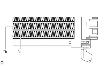
*a Element *b Fin Do not hold the quick heater assembly by the element or fin. Also, do not damage the quick heater assembly.
-
Foul odors may occur due to oil adhering to the quick heater assembly.
-
Firmly push in until a "click" sound is heard.
-
Check that the heights of the claw fitting surface on the heater case and the claw of the quick heater assembly are aligned.
-
-
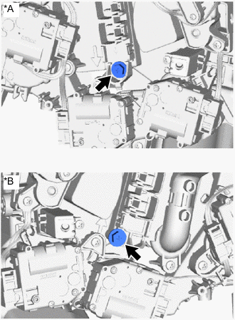
*A for LHD *B for RHD Install the quick heater assembly with the screw.
-
-
INSTALL HEATER COVER (w/o PTC Heater)
Tech Tips
Use the same procedure as for the quick heater assembly.
-
INSTALL COOLING UNIT PARTS
-
Install the cooling unit parts.
-
-
INSTALL HEATER GROMMET
-
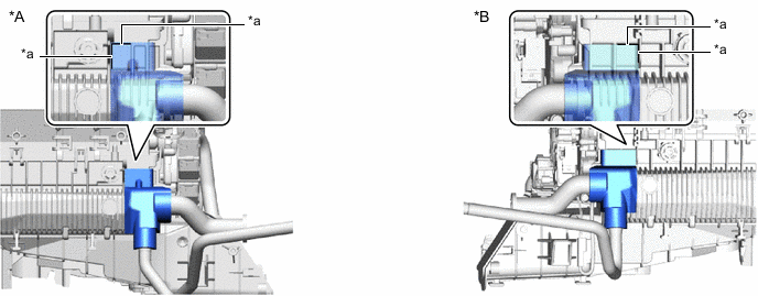
*A for LHD *B for RHD Face the heater grommet in the direction of the arrow shown in the illustration and install it.
-
-
INSTALL DRAIN COOLER HOSE (for Driver's Side)
-
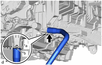
*a Protrusion *b Cutout Align the cutout of the drain cooler hose (for driver's side) with the protrusion of the heater case and install the drain cooler hose (for driver's side).
-
-
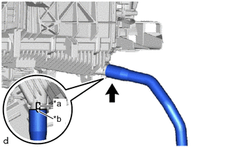
INSTALL DRAIN COOLER HOSE (for Front Passenger Side)
-
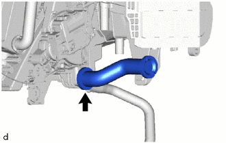
*a Protrusion *b Cutout Align the cutout of the drain cooler hose (for front passenger side) with the protrusion of the heater case and install the drain cooler hose (for front passenger side).
Note
Check that any remaining No. 3 cooling unit packing has been completely removed from the heater case, drain cooler hose (for front passenger side).
-
-
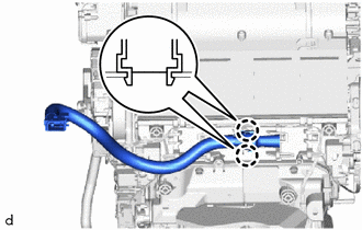
INSTALL NO. 2 COOLER UNIT DRAIN HOSE
-
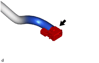
Install the No. 2 cooler unit drain hose.
Note
Check that any remaining No. 3 cooling unit packing has been completely removed from the No. 2 cooler unit drain hose.
-
-
INSTALL NO. 3 COOLING UNIT PACKING
-
Install a new No. 3 cooling unit packing in the position shown in the illustration.
Note
Check that any remaining No. 3 cooling unit packing has been completely removed from the heater case, drain cooler hose (for front passenger side) and No. 2 cooler unit drain hose.
*A for LHD *B for RHD *a Specified Application Position for Packing - -
-
-
INSTALL COOLER THERMISTOR (ROOM TEMPERATURE SENSOR)
-
Install the cooler thermistor (room temperature sensor) to the aspirator.
-
-
INSTALL ASPIRATOR
-
Attach the claw to install the aspirator.
-
-
INSTALL BLOWER ASSEMBLY