| DTC Code | DTC Name |
|---|---|
| B14B9 | Open in Ion Generator Circuit |
DESCRIPTION
The ion generator sub-assembly operates when both the ion generator switch and the blower switch are on. The air conditioning amplifier assembly sends a drive signal to the ion generator sub-assembly. When the ion generator sub-assembly receives the drive signal and starts to operate, it outputs an operation condition signal to the air conditioning amplifier assembly.
| DTC No. | Detection Item | DTC Detection Condition | Trouble Area | Memory |
|---|---|---|---|---|
| B14B9 | Open in Ion Generator Circuit |
|
|
Memorized |
CAUTION / NOTICE / HINT
Inspect the fuses for circuits related to this system before performing the following procedure.
PROCEDURE
- Click here
PERFORM ACTIVE TEST USING GTS (ION GENERATOR)
-
Connect the GTS to the DLC3.
-
Turn the power switch on (IG).
-
Turn the GTS on.
-
Enter the following menus: Body Electrical / Air Conditioner / Active Test.
-
Perform the Active Test according to the display on the GTS.
- Body Electrical > Air Conditioner > Active Test
Tester Display Measurement Item Control Range Diagnostic Note Ion Generator Ion generator sub-assembly OFF or ON - -
-
- Body Electrical > Air Conditioner > Active Test
Tester Display Ion Generator -
-
-
-
OK Ion generator sub-assembly operates normally. Result Proceed to OK NG - Body Electrical > Air Conditioner > Active Test
- OK
REPLACE AIR CONDITIONING AMPLIFIER ASSEMBLYClick here
- NGClick here
-
- Click here
CHECK HARNESS AND CONNECTOR (ION GENERATOR SUB-ASSEMBLY - BATTERY AND BODY GROUND)
-
Disconnect the G89 ion generator sub-assembly connector.
-
Measure the voltage according to the value(s) in the table below.
Standard Voltage Tester Connection Switch Condition Specified Condition G89-1 (IG) -Body ground Power switch on (IG) 11 to 14 V G89-1 (IG) -Body ground Power switch off Below 1 V -
Measure the resistance according to the value(s) in the table below.
Standard Resistance Tester Connection Condition Specified Condition G89-4 (GND) - Body ground Always Below 1 Ω Result Proceed to OK NG
- OKClick here
- NG
REPAIR OR REPLACE HARNESS OR CONNECTOR
-
- Click here
CHECK HARNESS AND CONNECTOR (ION GENERATOR SUB-ASSEMBLY - AIR CONDITIONING AMPLIFIER ASSEMBLY)
-
Disconnect the G89 ion generator sub-assembly connector.
-
Disconnect the G65 air conditioning amplifier assembly connector.
-
Measure the resistance according to the value(s) in the table below.
Standard Resistance Tester Connection Condition Specified Condition G65-26 (NAIN) - G89-3 (IG+) Always Below 1 Ω G65-7 (NANO) - G89-2 (PCL) Always Below 1 Ω G65-26 (NAIN) or G89-3 (IG+) - Other terminals and body ground Always 10 kΩ or higher G65-7 (NANO) or G89-2 (PCL) - Other terminals and body ground Always 10 kΩ or higher Result Proceed to OK NG
- OKClick here
- NG
REPAIR OR REPLACE HARNESS AND CONNECTOR
-
- Click here
CHECK AIR CONDITIONING AMPLIFIER ASSEMBLY
-
Disconnect the ion generator sub-assembly connector.
-
Measure the voltage according to the value(s) in the table below.
Standard Resistance Tester Connection Switch Condition Specified Condition G89-3 (IG+) - Body ground
-
Power switch on (IG)
-
Blower switch off
-
"nanoe" display: Off
4.75 to 5.25 V Result Proceed to OK NG -
- OKClick here
- NG
REPLACE AIR CONDITIONING AMPLIFIER ASSEMBLYClick here
-
- Click here
CHECK ION GENERATOR SUB-ASSEMBLY
-
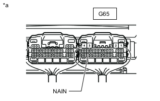
*a Component with harness connected
(Air Conditioning Amplifier Assembly)
Measure the voltage according to the value(s) in the table below.
Standard Resistance Tester Connection Switch Condition Specified Condition G65-26 (NAIN) - Body ground
-
Power switch on (IG)
-
Blower switch off
-
"nanoe" display: Off
Below 2.2 V Result Proceed to OK NG -
- OK
REPLACE AIR CONDITIONING AMPLIFIER ASSEMBLYClick here
- NG
REPLACE ION GENERATOR SUB-ASSEMBLYClick here
-