AIR CONDITIONING SYSTEM, Diagnostic DTC:B1469
| DTC Code | DTC Name |
|---|---|
| B1469 | Infrared Ray Sensor Circuit |
DESCRIPTION
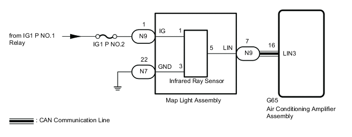
The infrared ray sensor, which is installed on the rear roof, detects human body temperature and controls the heater and air conditioner "AUTO" mode in 4 zones. Signals are transmitted to the air conditioning amplifier via the LIN communication line. This DTC is output when the temperature of the physical object is detected as -30°C (-22°F) or less, or 80°C (176°F) or more for 10 seconds or more.
| DTC No. | Detection Item | DTC Detection Condition | Trouble Area | Memory |
|---|---|---|---|---|
| B1469 | Infrared Ray Sensor Circuit |
|
|
Memorized |
WIRING DIAGRAM
CAUTION / NOTICE / HINT
Note
Inspect the fuses for circuits related to this system before performing the following procedure.
PROCEDURE
-
CHECK HARNESS AND CONNECTOR (MAP LIGHT ASSEMBLY - BATTERY AND BODY GROUND)
-
Disconnect the map light assembly connector.
-
Measure the resistance according to the value(s) in the table below.
Standard Resistance Tester Connection Condition Specified Condition N7-22 (GND) - Body ground Always Below 1 Ω -
Measure the voltage according to the value(s) in the table below.
Standard Voltage Tester Connection Switch Condition Specified Condition N9-1 (IG) - Body ground Power switch on (IG) 11 to 14 V Power switch off Below 1 V Result Proceed to OK NG
NG 
REPAIR OR REPLACE HARNESS OR CONNECTOR
OK 
-
-
CHECK HARNESS AND CONNECTOR (MAP LIGHT ASSEMBLY - AIR CONDITIONING AMPLIFIER ASSEMBLY)
-
Disconnect the N9 map light assembly connector.
-
Disconnect the G65 air conditioning amplifier assembly connector.
-
Measure the resistance according to the value(s) in the table below.
Standard Resistance Tester Connection Condition Specified Condition N9-7 (LIN) - G65-16 (LIN3) Always Below 1 Ω N9-7 (LIN) or G65-16 (LIN3) - Other terminals and body ground Always 10 kΩ or higher Result Proceed to OK NG
NG
REPAIR OR REPLACE HARNESS OR CONNECTOR
OK
-
-
CHECK AIR CONDITIONING AMPLIFIER ASSEMBLY (OUTPUT SIGNAL)
-
Disconnect N9 map light assembly connector.
-
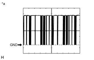
*a Waveform Using an oscilloscope, check the waveform.
Item Content Tester Connection N9-7 (LIN) - Body ground Tool Setting 2 V/DIV., 20 ms/DIV. Condition Power switch on (IG) OK The waveform displays properly. Result Proceed to OK NG
NG
REPLACE AIR CONDITIONING AMPLIFIER ASSEMBLY Click here
OK
-
-
CHECK MAP LIGHT ASSEMBLY (OUTPUT SIGNAL)
-
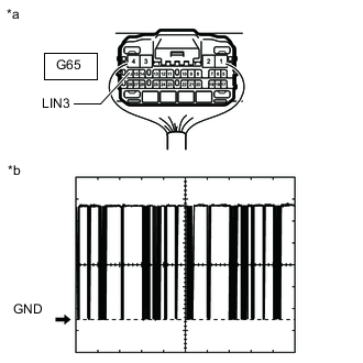
*a Component with harness connected
(Air Conditioning Amplifier Assembly)
*b Waveform Using an oscilloscope, check the waveform.
Item Content Tester Connection G65-16 (LIN3) - Body ground Tool Setting 2 V/DIV., 20 ms/DIV. Condition Power switch on (IG) OK The waveform displays properly. Result Proceed to OK NG
OK
REPLACE AIR CONDITIONING AMPLIFIER ASSEMBLY Click here
NG
-
-
INSPECT MAP LIGHT ASSEMBLY
-
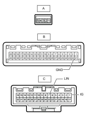
Remove the map light assembly.
-
Remove the infrared ray sensor from the map light assembly.
-
Measure the resistance according to the value(s) in the table below.
Standard Resistance Tester Connection Condition Specified Condition A-1 - C-1(IG) Always Below 1 Ω A-3 - B-22 (GND) Always Below 1 Ω A-5 - 7 (LIN) Always Below 1 Ω Result Proceed to OK NG
OK
REPLACE INFRARED RAY SENSOR Click here
NG
REPLACE MAP LIGHT ASSEMBLY Click here
-