AIR CONDITIONING SYSTEM, Diagnostic DTC:B1468
| DTC Code | DTC Name |
|---|---|
| B1468 | Room Temperature Sensor Circuit (Rear Passenger Side) |
DESCRIPTION
The No. 2 room temperature sensor detects the cabin temperature and controls the air conditioning system "AUTO" mode. The resistance of the No. 2 room temperature sensor changes according to changes in cabin temperature. The resistance value increases when the cabin temperature is low, and, conversely, decreases when the cabin temperature is high. The rear multiplex network door ECU sends the No. 2 room temperature sensor signal to the air conditioner amplifier assembly via CAN communication. The rear multiplex network ECU outputs voltage (5 V) to the No. 2 room temperature sensor, and reads changes in the voltage associated with changes in the resistance of the ambient temperature sensor.
The rear multiplex network door ECU sends the read signal to the air conditioning amplifier via the CAN communication line. The rear door ECU applies voltage (5 V) to the rear room temperature sensor and reads voltage changes as the resistance of the rear room temperature sensor changes. This sensor also sends the appropriate signals to the rear multiplex network door ECU.
| DTC No. | Detection Item | DTC Detection Condition | Trouble Area | Memory |
|---|---|---|---|---|
| B1468 | Room Temperature Sensor Circuit (Rear Passenger Side) |
|
|
Memorized |
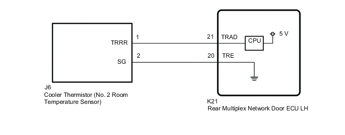
WIRING DIAGRAM
Figure 1. for LHD:

Figure 2. for RHD:
CAUTION / NOTICE / HINT
Note
The air conditioning system uses the CAN communication system. First, confirm that there is no malfunction in the CAN communication system. Refer to the How to Proceed with Troubleshooting procedure.
PROCEDURE
-
READ VALUE USING GTS (ROOM TEMPERATURE SENSOR)
-
Connect the GTS to the DLC3.
-
Turn the power switch on (IG).
-
Turn the GTS on.
-
Enter the following menus: Body Electrical / Air Conditioner / Data List.
-
Read the Data List according to the display on the GTS.
Body Electrical > Air Conditioner > Data ListTester Display Measurement Item Range Normal Condition Diagnostic Note Room Temp Sensor (Rear) Cooler (rear room temp. sensor) thermistor Min.: -6.50°C (20.30°F)
Max.: 57.25°C (135.05°F)
Actual cabin temperature displayed Cooler thermistor system malfunction
-
When open circuit: -6.50°C (20.30°F)
-
When short circuit: 57.25°C (135.05°F)
Body Electrical > Air Conditioner > Data ListTester Display Room Temp Sensor (Rear) OK The display is as specified in the normal condition column. Result Proceed to OK NG -
OK 
REPLACE AIR CONDITIONING AMPLIFIER ASSEMBLY Click here
NG 
-
-
INSPECT COOLER THERMISTOR (NO. 2 ROOM TEMPERATURE SENSOR)
-
Remove the cooler thermistor (No. 2 room temperature sensor).
-
Inspect the cooler thermistor (No. 2 room temperature sensor).
Result Proceed to OK NG
NG
REPLACE COOLER THERMISTOR (NO. 2 ROOM TEMPERATURE SENSOR) Click here
OK
-
-
CHECK HARNESS AND CONNECTOR (REAR MULTIPLEX NETWORK DOOR ECU - COOLER THERMISTOR (NO. 2 ROOM TEMPERATURE SENSOR))
-
for LHD:
-
Disconnect the K7 rear multiplex network door ECU RH connector.
-
Disconnect the J2 cooler thermistor (No. 2 room temperature sensor) connector.
-
Measure the resistance according to the value(s) in the table below.
Standard Resistance Tester Connection Condition Specified Condition K7-20 (TRE) - J2-2 (SG) Always Below 1 Ω K7-21 (TRAD) - J2-1 (TRRR) Always Below 1 Ω K7-20 (TRE) or J2-2 (SG) - Other terminals and body ground Always 10 kΩ or higher K7-21 (TRAD) or J2-1 (TRRR) - Other terminals and body ground Always 10 kΩ or higher
-
-
for RHD:
-
Disconnect the K21 rear multiplex network door ECU LH connector.
-
Disconnect the J6 cooler thermistor (No. 2 room temperature sensor) connector.
-
Measure the resistance according to the value(s) in the table below.
Standard Resistance Tester Connection Condition Specified Condition K21-20 (TRE) - J6-2 (SG) Always Below 1 Ω K21-21 (TRAD) - J6-1 (TRRR) Always Below 1 Ω K21-20 (TRE) or J6-2 (SG) - Other terminals and body ground Always 10 kΩ or higher K21-21 (TRAD) or J6-1 (TRRR) - Other terminals and body ground Always 10 kΩ or higher
-
-
Measure the resistance according to the value(s) in the table below.
Result Result Proceed to OK (for LHD) A OK (for RHD) B NG C
A
REPLACE REAR MULTIPLEX NETWORK DOOR ECU RH Click here
B
REPLACE REAR MULTIPLEX NETWORK DOOR ECU LH Click here
C
REPAIR OR REPLACE HARNESS OR CONNECTOR
-