PROCEDURE
- Click here
INSTALL FUEL FILLER OPENING LID SUB-ASSEMBLY
-
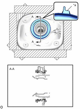
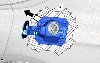
*a Rib Install the fuel tank filler pipe shield with the rib facing upward as shown in the illustration.
-
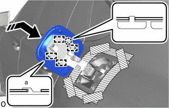
*1 Fuel Inlet Box Ring - - Install the fuel inlet box ring to the fuel tank filler pipe shield as shown in the illustration.
Tip:Put the cut in the fuel inlet box ring downward.
-
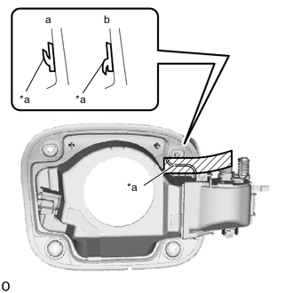
*a Lip 
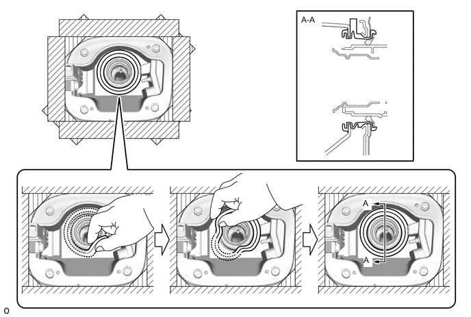
Protective Tape Apply protective tape to the fuel filler opening lid sub-assembly as shown in the illustration.
Note:
-
Apply protective tape with the lip appearing as shown in the illustration (a).
-
Check that lip is not deformed as shown in the illustration (b).
Tip:This step is not required when using a new part with tape already applied.
-
-

Install in this Direction Insert the fuel filler opening lid sub-assembly as shown in the illustration.
-
*a Protective Tape Remove the protective tape as shown in the illustration.
Tip:Use the same procedure to remove the tape when using a new part with tape already applied.
-
Install the fuel filler opening lid sub-assembly with the 4 screws.
-
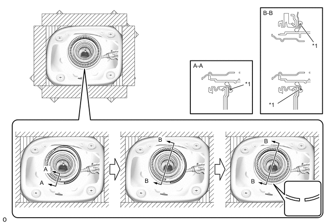
Install the fuel tank filler pipe shield as shown in the illustration.
-
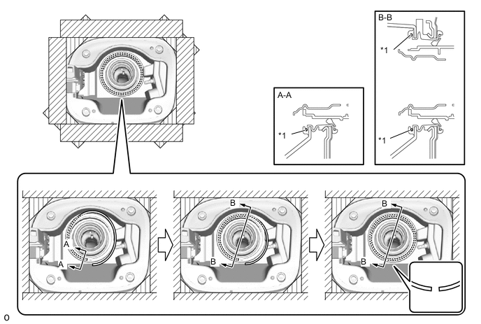
*1 Fuel Inlet Box Ring - - Install the fuel inlet box ring to the fuel tank filler pipe shield as shown in the illustration.
Tip:Put the cut in the fuel inlet box ring downward.
-
- Click here
INSTALL FUEL TANK CAP ASSEMBLY
-
Attach the clamp.
-
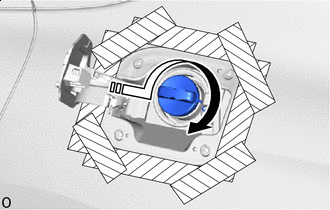
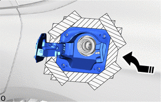
Install in this Direction Turn the fuel tank cap assembly in the direction of the arrow shown in the illustration to install it.
-
- Click here
INSTALL FUEL FILLER OPENING LID ASSEMBLY
-
Install in this Direction Slide in the direction of the arrow shown in the illustration to attach the part (a) at 4 positions and the claw and install the fuel filler opening lid assembly.
-
Remove the protective tape.
-
- Click here
INSTALL REAR WHEEL HOUSE LINER LH
- Click here
INSTALL ROCKER PANEL MOULDING PROTECTOR LH
- Click here
INSTALL REAR TIRE LH
- Click here
INSTALL FUEL LID LOCK WITH MOTOR ASSEMBLY