Click here
-
 Note:
Note:
-
DTCs may be output when connectors are disconnected during inspection. Therefore, be sure to clear the DTCs using the GTS once the inspection has been completed.
-
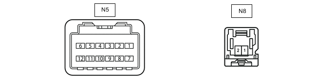
Do not apply excessive force to the N5 and N8 object recognition camera connector.
CHECK OBJECT RECOGNITION CAMERA
-
Measure the voltage and resistance according to the value(s) in the table below.
Terminal No. (Symbol) Wiring Color Terminal Description Condition Specified Condition N5-7 (IGB) - Body ground R - Body ground Power source Power switch on (IG) 11 to 14 V Power switch off Below 1 V N8-1 (IG1) - Body ground B - Body ground Power source Power switch on (IG) 11 to 14 V Power switch off Below 1 V N5-1 (HTR) - Body ground BR - Body ground Object recognition camera internal heater operation signal With power switch on (IG) and object recognition camera internal heater not operating 11 to 14 V With power switch on (IG) and object recognition camera internal heater operating Below 1 V N5-10 (GND) - Body ground BR - Body ground Ground Always Below 1 Ω -
Measure the waveform according to the value(s) in the table below.
Terminal No. (Symbol) Wiring Color Terminal Description Condition Specified Condition N5-2 (STRV) - N5-10 (GND) GR - BR LIN communication signal Power switch on (IG) Pulse generation
(See waveform 1)
-
WAVEFORM 1
-
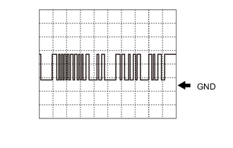
LIN communication signal
Item Content Terminal Name Between N5-2(STRV) and N5-10 (GND) Tester Range 5 V/DIV., 1 msec./DIV. Condition Power switch on (IG) Tip:Oscilloscope waveform samples are provided here for informational purposes. Noise and fluttering waveforms have been omitted.
-
-
-
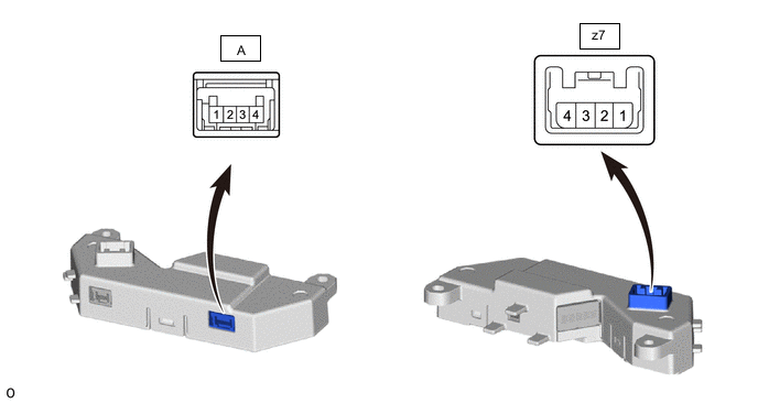
CHECK STEERING VIBRATION AND HEATER ECU
-
Measure the voltage and resistance according to the value(s) in the table below.
Terminal No. (Symbol) Terminal Description Condition Specified Condition z7-4 (IG) - z7-1 (GND) Power source Power switch on (IG) 11 to 14 V Power switch off Below 1 V A-3 (M+) - z7-1 (GND) Steering vibration operation signal With power switch on (IG) and steering vibration operating Pulse generation With power switch on (IG) and steering vibration not operating Below 1 V z7-1 (GND) - Body ground Ground Always Below 1 Ω -
Measure the waveform according to the value(s) in the table below.
Terminal No. (Symbol) Terminal Description Condition Specified Condition z7-2 (LIN1) - z7-1 (GND) LIN communication signal Power switch on (IG) Pulse generation
-