PROCEDURE
- Click here
INSPECT OIL PUMP RELIEF VALVE
-
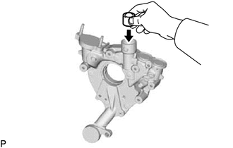
Coat the valve with engine oil, then check that it falls smoothly into the valve hole by its own weight. If the valve does not fall smoothly, replace the timing chain cover assembly.
-
- Click here
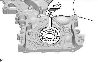
INSPECT OIL PUMP ROTOR SET
-
Apply engine oil to the drive rotor and driven rotor.
-
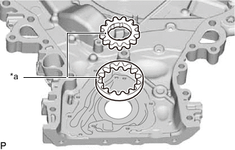
*a Mark Place the drive rotor and driven rotor into the timing chain cover assembly with the marks facing upward.
-
Check the tip clearance.
-
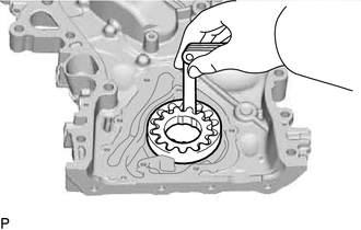
Using a feeler gauge, measure the clearance between the oil pump drive rotor and oil pump driven rotor tips.
Standard Tip Clearance 0.06 to 0.16 mm (0.00236 to 0.00630 in.) Maximum Tip Clearance 0.16 mm (0.00630 in.) If the clearance is more than the maximum, replace the timing chain cover assembly.
-
-
Check the rotor side clearance.
-
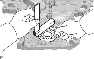
Using a feeler gauge and precision straightedge, measure the clearance between the oil pump drive rotor, oil pump driven rotor and precision straightedge.
Standard Side Clearance 0.030 to 0.09 mm (0.00118 to 0.00354 in.) Maximum Side Clearance 0.09 mm (0.00354 in.) If the clearance is more than the maximum, replace the drive and driven rotors as a set. If necessary, replace the timing chain cover assembly.
-
-
Check the body clearance.
-
Using a feeler gauge, measure the clearance between the oil pump driven rotor and oil pump body.
Standard Body Clearance 0.250 to 0.325 mm (0.00984 to 0.0128 in.) Maximum Body Clearance 0.325 mm (0.0128 in.) If the clearance is more than the maximum, replace the drive and driven rotors as a set. If necessary, replace the timing chain cover assembly.
-
-