DYNAMIC RADAR CRUISE CONTROL SYSTEM(for Stereo Camera Type) TERMINALS OF ECU
-
CHECK DRIVING SUPPORT ECU ASSEMBLY

Note
Do not apply excessive force to the connector. If a force of 10 kg or more is applied, the connector may be broken.
Terminal No. (Symbol) Wiring Color Terminal Description Condition Specified Condition G67-30 (B) - G67-28 (GND) LA-V - LA Power source Power switch on (IG) 11 to 14 V Power switch off Below 1 V G67-37 (SPSW) - G67-28 (GND) Y - LA Steering pad switch assembly signal (distance control signal) Power switch on (IG), vehicle-to-vehicle distance control switch (steering pad switch assembly) off 4.75 to 5.25 V Power switch on (IG), vehicle-to-vehicle distance control switch (steering pad switch assembly) on Below 1 V -
CHECK HYBRID VEHICLE CONTROL ECU ASSEMBLY
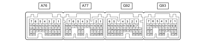
Terminal No. (Symbol) Wiring Color Terminal Description Condition Specified Condition A77-8 (STP) - Body ground R - Body ground Stop light switch assembly signal Brake pedal depressed 7.5 to 14 V Brake pedal released 0 to 1.5 V A77-21 (ST1-) - Body ground B - Body ground Stop light switch assembly signal Power switch on (IG), brake pedal depressed 0 to 1.5 V Power switch on (IG), brake pedal released 7.5 to 14 V G93-9 (CCS) - Body ground SB - Body ground Cruise control switch circuit Cruise control switch not pushed 1 MΩ or higher Cruise control main switch pushed Below 2.5 Ω CANCEL switch ON 228 to 252 Ω +RES switch ON 599 to 661 Ω -SET switch ON 1463 to 1617 Ω -
CHECK MILLIMETER WAVE RADAR SENSOR