Click here
PROCEDURE
- Click here
INSPECT PURGE VSV
-
Measure the resistance according to the value(s) in the table below.
Standard Resistance Tester Connection Condition Specified Condition D10-1 - D10-2 20°C (68°F) 23 to 26 Ω D10-1 - Body ground Always 10 MΩ or higher D10-2 - Body ground Always 10 MΩ or higher Tip:When measuring the coil resistance make sure that the surface temperature of the purge VSV is 20°C.
If the result is not as specified, replace the purge VSV.
-
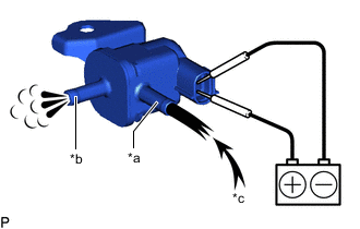
*a Port E *b Port F *c Air Apply auxiliary battery voltage between the terminals of the purge VSV and check that the following occurs when blowing air into the port E.
OK Tester Connection Condition Specified Condition D10-1 - D10-2 Auxiliary battery voltage applied between the terminals Air flows from port F Auxiliary battery voltage not applied between the terminals Air does not flow If the result is not as specified, replace the purge VSV.
-