PROCEDURE
- Click here
INSTALL HV BATTERY JUNCTION BLOCK ASSEMBLY
CAUTION:Be sure to wear insulated gloves and protective goggles.
-
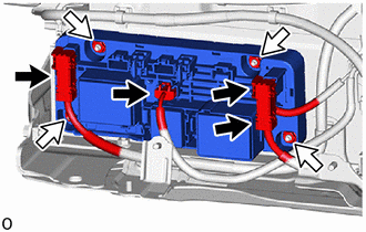
Install the HV battery junction block assembly with the 4 nuts.
7.5 N*m 76 kgf*cm 66 in.*lbf Note:
-
Do not drop the HV battery junction block assembly, strike it with tools or subject it to impact.
-
If the HV battery junction block assembly is subjected to an impact, replace it with a new one.
-
-
Connect the 4 connectors.
Note:Make sure that the connector is connected securely.
-
- Click here
INSTALL NO. 1 HYBRID BATTERY SHIELD SUB-ASSEMBLY
- Click here
INSTALL UPPER HV BATTERY COVER PANEL
- Click here
INSTALL HV BATTERY ASSEMBLY
- Click here
PERFORM CURRENT SENSOR OFFSET LEARNING
Tip:Perform this procedure when the HV battery junction block assembly or battery ECU assembly has been replaced.
-
Connect the GTS to the DLC3.
-
Turn the power switch on (READY).
-
Perform a road test.
Note:Accelerate and decelerate gently. Avoid rapid acceleration and deceleration.
-
Enter the following menus: Powertrain / HV Battery / Data List / Hybrid Battery Current.
- Powertrain > HV Battery > Data List
Tester Display Hybrid Battery Current -
-
-
-
- Powertrain > HV Battery > Data List
-
Drive the vehicle with the value of Data List item "Hybrid Battery Current" between -50 A and 50 A.
Tip:Distance and driving time are not specified.
-
Turn the power switch off and leave the vehicle for 30 seconds or more.
-
Turn the power switch on (IG).
-
Enter the following menus: Powertrain / HV Battery / Data List / Hybrid Battery Current.
- Powertrain > HV Battery > Data List
Tester Display Hybrid Battery Current -
-
-
-
- Powertrain > HV Battery > Data List
-
Check that the value of "Hybrid Battery Current" is between -0.5 A and 0.5 A with the power switch on (IG).
Note:If the value is outside the specified range, perform the road test again.
Tip:
-
When the power switch is on (IG), if value of "Hybrid Battery Current" is between -0.5 A and 0.5 A, current sensor offset learning has been completed.
-
Even if the current sensor offset learning is not complete, the current sensor value will be corrected by repeating the road test a maximum of 7 times.
-
-
-