MOTOR GENERATOR CONTROL SYSTEM, Diagnostic DTC:P0E3116, P0E3117, P0E311F
| DTC Code | DTC Name |
|---|---|
| P0E3116 | DC/DC Converter Voltage Sensor "A"(VL) Circuit Voltage Below Threshold |
| P0E3117 | DC/DC Converter Voltage Sensor "A"(VL) Circuit Voltage Above Threshold |
| P0E311F | DC/DC Converter Voltage Sensor "A"(VL) Circuit Intermittent |
DESCRIPTION
The motor generator control ECU, which is built into the inverter with converter assembly, detects pre-boosting high voltage (VL) using the voltage sensor in the boost converter to control boosting. The motor generator control ECU also monitors the boost converter voltage sensor signal line and detects malfunctions.
| DTC No. | Detection Item | DTC Detection Condition | Trouble Area | MIL | Warning Indicate |
|---|---|---|---|---|---|
| P0E3116 | DC/DC Converter Voltage Sensor "A"(VL) Circuit Voltage Below Threshold | Boost converter voltage (VL) signal is stuck (Low) (1 trip detection logic) |
Inverter with converter assembly | Comes on | Master Warning Light: Comes on |
| P0E3117 | DC/DC Converter Voltage Sensor "A"(VL) Circuit Voltage Above Threshold | Boost converter voltage (VL) signal is stuck (High) (1 trip detection logic) |
Inverter with converter assembly | Comes on | Master Warning Light: Comes on |
| P0E311F | DC/DC Converter Voltage Sensor "A"(VL) Circuit Intermittent | A generator inverter current sensor characteristic malfunction and boost converter voltage (VL) signal is stuck (Low) or (High) detected when DTC P0C7917, P0D3319, P1C5D19 or P1C5F19 is stored. (1 trip detection logic) |
Inverter with converter assembly | Comes on | Master Warning Light: Comes on |
| DTC No. | Data List |
|---|---|
| P0E3116 P0E3117 P0E311F |
|
CONFIRMATION DRIVING PATTERN
Tech Tips
After repair has been completed, clear the DTC and then check that the vehicle has returned to normal by performing the following All Readiness check procedure.
-
Connect the GTS to the DLC3.
-
Turn the power switch on (IG) and turn the GTS on.
-
Clear the DTCs (even if no DTCs are stored, perform the clear DTC procedure).
-
Turn the power switch off and wait for 2 minutes or more.
-
Turn the power switch on (IG) and turn the GTS on.
-
Turn the power switch on (READY) and wait for 5 seconds or more.
-
Enter the following menus: Powertrain / Motor Generator / Utility / All Readiness.
-
Check the DTC judgment result.
Tech Tips
-
If the judgment result shows NORMAL, the system is normal.
-
If the judgment result shows ABNORMAL, the system has a malfunction.
-
If the judgment result shows INCOMPLETE, perform driving pattern again.
-
PROCEDURE
-
CHECK DTC OUTPUT
-
Connect the GTS to the DLC3.
-
Turn the power switch on (IG).
-
Enter the following menus: Powertrain / Hybrid Control and Motor Generator / Trouble Codes.
Powertrain > Hybrid Control > Trouble Codes
Powertrain > Motor Generator > Trouble Codes -
Check for DTCs.
Result Result Proceed to P0E3116 only is output. A P0E3117 or P0E311F only is output, and none of the DTCs in the table below are output. B DTCs of hybrid control system in the tables below are output. C DTCs of motor generator control system in the tables below are output. D System Relevant DTC Hybrid control system P0AD915 Hybrid/EV Battery Positive Contactor Circuit Short to Auxiliary Battery or Open P0ADD15 Hybrid/EV Battery Negative Contactor Circuit Short to Auxiliary Battery or Open P1C8449 High Voltage Power Resource Circuit Short during Ready ON P312387 Lost Communication with Drive Motor Control Module "A" from Hybrid/EV Control Module Missing Message Motor generator control system P312487 Lost Communication between Drive Motor "A" and HV ECU Missing Message Tech Tips
P0E3116, P0E3117 or P0E311F may be stored due to a malfunction which also causes the DTCs in the preceding table to be stored. In this case, first troubleshoot the output DTCs in the preceding table. Then, perform a test to attempt to reproduce the problems, and check that no DTCs are output.
-
Turn the power switch off.
B 
REPLACE INVERTER WITH CONVERTER ASSEMBLY Click here
C
GO TO DTC CHART (HYBRID CONTROL SYSTEM) Click here
D
GO TO DTC CHART (MOTOR GENERATOR CONTROL SYSTEM) Click here
A 
-
-
CHECK FREEZE FRAME DATA
-
Connect the GTS to the DLC3.
-
Turn the power switch on (IG).
-
Enter the following menus: Powertrain / Motor Generator / Trouble Codes.
-
Read the freeze frame data of DTC P0E3116
Powertrain > Motor Generator > Trouble CodesResult Result Proceed to "VH Voltage" is less than 55 V. A "VH Voltage" is 55 V or more. B -
Turn the power switch off.
B
REPLACE INVERTER WITH CONVERTER ASSEMBLY Click here
A
-
-
CLEAR DTC
-
Connect the GTS to the DLC3.
-
Turn the power switch on (IG).
-
Enter the following menus: Powertrain / Hybrid Control and Motor Generator / Trouble Codes.
-
Read and record the DTCs and freeze frame data.
Powertrain > Hybrid Control > Trouble Codes
Powertrain > Motor Generator > Trouble Codes -
Clear the DTCs and freeze frame data.
Powertrain > Hybrid Control > Clear DTCs
Powertrain > Motor Generator > Clear DTCs -
Turn the power switch off.
Result Proceed to NEXT
NEXT
-
-
CHECK DTC OUTPUT (HYBRID CONTROL)
-
Connect the GTS to the DLC3.
-
With the vehicle stopped, apply the parking brake and turn the power switch on (READY).
Tech Tips
-
If the power switch could not be turned on (READY), turn the power switch off and check for DTCs after turning the power switch on (READY) again.
-
Because P300449 uses 2 trip detection logic, the DTC detection conditions need to be met 2 times.
-
-
Ensure the safety of the areas in front and at the back of the vehicle.
-
Move the shift lever to select shift state drive (D) and depress both the accelerator pedal and brake pedal at the same time.
Tech Tips
Depressing both the accelerator pedal and brake pedal at the same time causes the HV battery current to flow and ensures that there is no problem with the high-voltage wiring.
-
Enter the following menus: Powertrain / Hybrid Control / Trouble Codes.
-
Check for DTCs.
Powertrain > Hybrid Control > Trouble CodesResult Result Proceed to P1C8449 is output, or no DTCs are output. A Power switch could not be turned on (READY) and DTC P300449 is output. B -
Turn the power switch off.
B
GO TO DTC CHART (P300449) Click here
A
-
-
CHECK CONNECTOR CONNECTION CONDITION (HYBRID VEHICLE CONTROL ECU ASSEMBLY CONNECTOR)
Result Proceed to OK NG
-
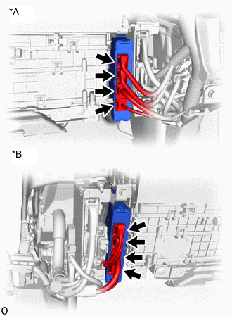
*A for LHD *B for RHD Check the connector connections and contact pressure of the relevant terminals for the hybrid vehicle control ECU assembly connectors.
OK The connectors are connected securely and there are no contact pressure problems. Result Proceed to OK NG
NG
CONNECT SECURELY
OK
-
-
CHECK CONNECTOR CONNECTION CONDITION (FLOOR WIRE CONNECTOR)
Result Result Proceed to OK A NG (The connector is not connected securely.) B NG (The terminals are not making secure contact or are deformed, or water or foreign matter exists in the connector.) C
-
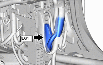
Check the connection condition of the LG1 floor wire connector and the contact pressure of each terminal. Check the terminals for deformation, and check the connector for water ingress and foreign matter.
OK - The connector is connected securely. - The terminals are not deformed and are connected securely. - No water or foreign matter in the connector. Result Result Proceed to OK A NG (The connector is not connected securely.) B NG (The terminals are not making secure contact or are deformed, or water or foreign matter exists in the connector.) C
B
CONNECT SECURELY
C
REPAIR OR REPLACE HARNESS OR CONNECTOR
A
-
-
CHECK CONNECTOR CONNECTION CONDITION (NO. 2 HV BATTERY PACK WIRE CONNECTOR)
Result Result Proceed to OK A NG (The connector is not connected securely.) B NG (The terminals are not making secure contact or are deformed, or water or foreign matter exists in the connector.) C
-
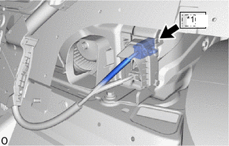
*1 Le1 Check the connection condition of the Le1 No. 2 HV battery pack wire connector and the contact pressure of each terminal. Check the terminals for deformation, and check the connector for water ingress and foreign matter.
OK - The connector is connected securely. - The terminals are not deformed and are connected securely. - No water or foreign matter in the connector. Result Result Proceed to OK A NG (The connector is not connected securely.) B NG (The terminals are not making secure contact or are deformed, or water or foreign matter exists in the connector.) C
B
CONNECT SECURELY
C
REPAIR OR REPLACE HARNESS OR CONNECTOR
A
-
-
CHECK CONNECTOR CONNECTION CONDITION (HV BATTERY JUNCTION BLOCK ASSEMBLY CONNECTOR)
Result Proceed to OK NG CAUTION:
Be sure to wear insulated gloves.
-
Check that the service plug grip is not installed.
Note
After removing the service plug grip, do not turn the power switch on (READY), unless instructed by the repair manual because this may cause a malfunction.
-
Remove the No. 10 HV battery shield panel.
-
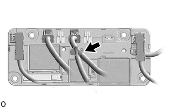
Check the connector connections and contact pressure of the relevant terminals of the HV battery junction block assembly connector.
OK The connectors are connected securely and there are no contact pressure problems. -
Install the No. 10 HV battery shield panel.
Result Proceed to OK NG
NG
CONNECT SECURELY
OK
-
-
CHECK HARNESS AND CONNECTOR (HYBRID VEHICLE CONTROL ECU ASSEMBLY - HV BATTERY JUNCTION BLOCK ASSEMBLY)
CAUTION:
Be sure to wear insulated gloves.
-
Check that the service plug grip is not installed.
Note
After removing the service plug grip, do not turn the power switch on (READY), unless instructed by the repair manual because this may cause a malfunction.
-
Disconnect the G92 hybrid vehicle control ECU assembly connector.
-
Remove the No. 10 HV battery shield panel.
-
Disconnect the e2 HV battery junction block assembly connector.
-
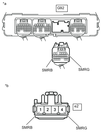
*a Rear view of wire harness connector
(to Hybrid Vehicle Control ECU Assembly)
*b Front view of wire harness connector
(to HV Battery Junction Block Assembly)
Measure the resistance according to the value(s) in the table below.
Standard Resistance Tester Connection Condition Specified Condition G92-5 (SMRB) - e2-1 (SMRB) Power switch off Below 1 Ω G92-1 (SMRG) - e2-4 (SMRG) Power switch off Below 1 Ω -
Reconnect the e2 HV battery junction block assembly connector.
-
Install the No. 10 HV battery shield panel.
-
Reconnect the G92 hybrid vehicle control ECU assembly connector.
Result Proceed to OK NG
NG
REPAIR OR REPLACE HARNESS OR CONNECTOR
OK
-
-
CHECK HARNESS AND CONNECTOR (HV BATTERY JUNCTION BLOCK ASSEMBLY - BODY GROUND)
CAUTION:
Be sure to wear insulated gloves.
-
Check that the service plug grip is not installed.
Note
After removing the service plug grip, do not turn the power switch on (READY), unless instructed by the repair manual because this may cause a malfunction.
-
Remove the No. 10 HV battery shield panel.
-
Disconnect the e2 HV battery junction block assembly connector.
-
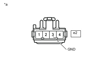
*a Front view of wire harness connector
(to HV Battery Junction Block Assembly)
Measure the resistance according to the value(s) in the table below.
Standard Resistance Tester Connection Condition Specified Condition e2-3 (GND) - Body ground Power switch off Below 1 Ω -
Reconnect the e2 HV battery junction block assembly connector.
-
Install the No. 10 HV battery shield panel.
Result Proceed to OK NG
NG
REPAIR OR REPLACE HARNESS OR CONNECTOR
OK
-
-
REPLACE HV BATTERY JUNCTION BLOCK ASSEMBLY
Result Proceed to NEXT
NEXT
-
CHECK HYBRID VEHICLE CONTROL ECU ASSEMBLY (CHECK FOR NORMAL OPERATION)
-
Install the service plug grip.
-
Turn the power switch on (IG).
-
Clear the DTCs.
Powertrain > Hybrid Control > Clear DTCs
Powertrain > Motor Generator > Clear DTCs -
Turn the power switch off and wait for 30 seconds or more.
-
Turn the power switch on (READY).
-
Enter the following menus: Powertrain / Hybrid Control / Data List / Hybrid Battery Voltage, VL-Voltage before Boosting.
-
According to the display on the GTS, read the Data List and monitor the values of "Hybrid Battery Voltage" and "VL-Voltage before Boosting" for 3 minutes.
Powertrain > Hybrid Control > Data ListTester Display VL-Voltage before Boosting Hybrid Battery Voltage Result Result Proceed to Difference between "Hybrid Battery Voltage" and "VL-Voltage before Boosting" is always less than 50 V. A Difference between "Hybrid Battery Voltage" and "VL-Voltage before Boosting" is 50 V or more. B -
Turn the power switch off.
A
END
B
REPLACE HYBRID VEHICLE CONTROL ECU ASSEMBLY Click here
-