| DTC Code | DTC Name |
|---|---|
| Pattern Select Switch EV Mode Circuit |
DESCRIPTION
The EV mode signal will be sent to the hybrid vehicle control ECU assembly when the EV mode switch (integration control & panel assembly) is operated. If the specified conditions are met, the system enters EV mode and the vehicle will be driven using EV mode. This signal is then transmitted from the hybrid vehicle control ECU assembly via CAN to the combination meter assembly to illuminate the EV mode indicator.
CAUTION / NOTICE / HINT
Depending on the condition of the hybrid control system and the driving conditions, the drive mode may not be able to be changed to EV mode and a warning message will be displayed on the multi-information display.
Under the following conditions, the drive mode will not be able to be changed to EV mode:
-
The hybrid control system is extremely hot.
-
-
After the vehicle has been parked in an extremely hot environment, driven at high speeds or the vehicle is climbing a slope, etc.
-
-
The hybrid control system is extremely cold.
-
-
After the vehicle has been parked in an extremely cold environment (approximately 0°C or less) for a long period of time.
-
-
The engine is warming up.
-
The SOC (State of Charge) of the HV battery is low.
-
-
The HV battery SOC displayed on the hybrid system indicator display is low.
-
-
The vehicle is being driven at a speed higher than the specified value.
-
-
The vehicle speed is approximately 30 km/h or higher.
-
-
The accelerator pedal is being fully depressed or the vehicle is climbing a slope.
-
The defroster is on.
-
DTCs are stored.
PROCEDURE
- Click here
ASK ABOUT VEHICLE CONDITION
-
Check if a buzzer sounded and a message was displayed on the multi-information display when attempting to enter EV mode.
Result Result Proceed to No buzzer sounded and no message was displayed on multi-information display. A A buzzer sounded and a message was displayed on multi-information display. B Tip:If a buzzer sounds and a message is displayed on the multi-information display, one or more of the EV mode entry conditions have not been met. Check that all of the EV mode entry conditions have been met before pressing the EV mode switch (integration control & panel assembly).
- AClick here
- B
END
-
- Click here
READ VALUE USING GTS (CAN BUS CHECK)
-
Connect the GTS to the DLC3.
-
Turn the power switch on (IG).
-
Turn the GTS on.
-
Enter the following menus: System Select / CAN Bus Check.
- CAN Bus Check
-
Result Result Proceed to All of the ECUs and sensors that are currently connected to the CAN communication system are displayed. A None of the ECUs and sensors that are currently connected to the CAN communication system are displayed, or some of them are not displayed. B -
Turn the power switch off.
- AClick here
- B
GO TO CAN COMMUNICATION SYSTEMClick here
-
- Click here
CHECK DTC OUTPUT (HEALTH CHECK)
-
Connect the GTS to the DLC3.
-
Turn the power switch on (IG).
-
Turn the GTS on.
-
Enter the following menus: System Select / Health Check.
-
Check for DTCs.
Result Result Proceed to No DTCs are output. A DTCs are output. B -
Turn the power switch off.
- AClick here
- B
GO TO DTC CHART
-
- Click here
READ VALUE USING GTS (EV MODE, EV MODE SWITCH)
-
Connect the GTS to the DLC3.
-
Turn the power switch on (IG).
-
Turn the GTS on.
-
Enter the following menus: Powertrain / Hybrid Control / Data List / EV Mode, EV Mode Switch.
- Powertrain > Hybrid Control > Data List
Tester Display EV Mode EV Mode Switch -
-
-
-
- Powertrain > Hybrid Control > Data List
-
Read the value displayed on the GTS.
- Powertrain > Hybrid Control > Data List
Tester Display Measurement Item Range Normal Condition EV Mode EV mode transition availability ON or OFF In EV mode: ON EV Mode Switch EV mode switch (integration control & panel assembly) condition ON or OFF EV mode switch (integration control & panel assembly) not pushed: OFF
EV mode switch (integration control & panel assembly) being pushed and held: ON
-
-
Result Result Proceed to The display changes according to the EV mode switch (integration control & panel assembly) operation. A The display does not change according to the EV mode switch (integration control & panel assembly) operation. B - Powertrain > Hybrid Control > Data List
-
Turn the power switch off.
- A
GO TO PROBLEM SYMPTOMS TABLEClick here
- BClick here
-
- Click here
INSPECT EV MODE SWITCH (INTEGRATION CONTROL & PANEL ASSEMBLY)
-
Inspect the EV mode switch (integration control & panel assembly).
Result Proceed to OK NG
- OKClick here
- NG
REPLACE EV MODE SWITCH (INTEGRATION CONTROL & PANEL ASSEMBLY)Click here
-
- Click here
CHECK HARNESS AND CONNECTOR (EV MODE SWITCH (INTEGRATION CONTROL & PANEL ASSEMBLY) - BODY GROUND)
-
Disconnect the G72 EV mode switch (integration control & panel assembly) connector.
-
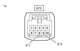
*1 for LHD *2 for RHD *a Front view of wire harness connector
(to EV Mode Switch (Integration Control & Panel Assembly))
Measure the resistance according to the value(s) in the table below.
Standard Resistance Table 1. for LHD: Tester Connection Condition Specified Condition G72-8 (E) - Body ground Power switch off Below 1 Ω Table 2. for RHD: Tester Connection Condition Specified Condition G72-9 (E) - Body ground Power switch off Below 1 Ω -
Reconnect the G72 EV mode switch (integration control & panel assembly) connector.
Result Proceed to OK NG
- OKClick here
- NG
REPAIR OR REPLACE HARNESS OR CONNECTOR
-
- Click here
CHECK HARNESS AND CONNECTOR (HYBRID VEHICLE CONTROL ECU ASSEMBLY - EV MODE SWITCH (INTEGRATION CONTROL & PANEL ASSEMBLY))
-
Disconnect the G93 hybrid vehicle control ECU assembly connector.
-
Disconnect the G72 EV mode switch (integration control & panel assembly) connector.
-
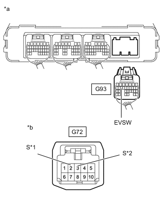
*1 for LHD *2 for RHD *a Rear view of wire harness connector
(to Hybrid Vehicle Control ECU Assembly)
*b Front view of wire harness connector
(to EV Mode Switch (Integration Control & Panel Assembly))
Measure the resistance according to the value(s) in the table below.
Standard Resistance Table 3. for LHD: Tester Connection Condition Specified Condition G93-15 (EVSW) - G72-2 (S) Power switch off Below 1 Ω G93-15 (EVSW) or G72-2 (S) - Body ground Power switch off 10 kΩ or higher Table 4. for RHD: Tester Connection Condition Specified Condition G93-15 (EVSW) - G72-3 (S) Power switch off Below 1 Ω G93-15 (EVSW) or G72-3 (S) - Body ground Power switch off 10 kΩ or higher -
Reconnect the G72 EV mode switch (integration control & panel assembly) connector.
-
Reconnect the G93 hybrid vehicle control ECU assembly connector.
Result Proceed to OK NG
- OK
REPLACE HYBRID VEHICLE CONTROL ECU ASSEMBLYClick here
- NG
REPAIR OR REPLACE HARNESS OR CONNECTOR
-