| DTC Code | DTC Name |
|---|---|
| Solenoid Valve Circuit |
DESCRIPTION
The cause of this malfunction may be the motor resolver.
Check the installation condition of the solenoids installed to each solenoid valve and transmission valve body.
| Area | Inspection | Step |
|---|---|---|
| Solenoid valve | Check internal resistance of each solenoid valve | 1, 2, 3 |
| Transmission valve body assembly | Check solenoid installation conditions | 4 |
CAUTION / NOTICE / HINT
This procedure is referenced from the procedures for each DTC.
If the following inspection results are normal, perform the next procedure for the referenced DTC.
PROCEDURE
- Click here
INSPECT SOLENOID (SL1), (SL2), (SL3) AND (SL4) VALVE
-
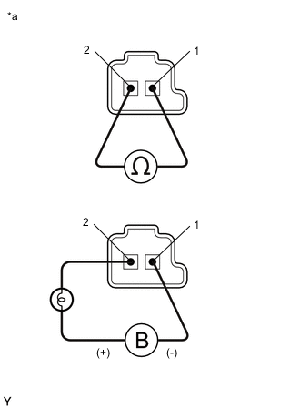
*a Component without harness connected
(Solenoid (SL1), (SL2), (SL3) and (SL4) Valves)
Remove the solenoid (SL1), (SL2), (SL3) and (SL4) valves.
for 2WD:
for AWD:
-
Measure the resistance according to the value(s) in the table below.
Standard Resistance Tester Connection Condition Specified Condition Terminal 1 of the solenoid (SL1) valve - terminal 2 20°C (68°F) 5.0 to 5.6 Ω Terminal 1 of the solenoid (SL2) valve - terminal 2 20°C (68°F) 5.0 to 5.6 Ω Terminal 1 of the solenoid (SL3) valve - terminal 2 20°C (68°F) 5.0 to 5.6 Ω Terminal 1 of the solenoid (SL4) valve - terminal 2 20°C (68°F) 5.0 to 5.6 Ω -
Connect a positive (+) lead from the battery with a 21 W bulb to terminal 2 and a negative (-) lead to terminal 1 of the solenoid valve connector. Check that the valve moves and makes an operating sound.
OK Valve moves and makes an operating sound. -
Install the solenoid (SL1), (SL2), (SL3) and (SL4) valves.
Result Proceed to OK NG
- OKClick here
- NG
REPLACE SOLENOID (SL1), (SL2), (SL3) OR (SL4) VALVE for 2WD:
REPLACE SOLENOID (SL1), (SL2), (SL3) OR (SL4) VALVEClick here
REPLACE SOLENOID (SL1), (SL2), (SL3) OR (SL4) VALVE for AWD:
REPLACE SOLENOID (SL1), (SL2), (SL3) OR (SL4) VALVEClick here
-
- Click here
INSPECT SOLENOID (SC1) AND (SC2) VALVE
-
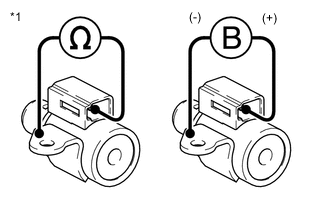
*1 Solenoid (SC1) and (SC2) Valves Remove the solenoid (SC1) and (SC2) valves.
for 2WD:
for AWD:
-
Measure the resistance according to the value(s) in the table below.
Standard Resistance Tester Connection Condition Specified Condition Terminal of solenoid (SC1) valve connector - Solenoid (SC1) valve body 20°C (68°F) 11 to 15 Ω Terminal of solenoid (SC2) valve connector - Solenoid (SC2) valve body 20°C (68°F) 11 to 15 Ω -
Connect a positive (+) lead from the battery to the terminal of the solenoid valve connector, and a negative (-) lead to the solenoid body. Check that the valve moves and makes an operating sound.
OK Valve moves and makes an operating sound. -
Install the solenoid (SC1) and (SC2) valves.
Result Proceed to OK NG
- OKClick here
- NG
REPLACE SOLENOID (SC1) OR (SC2) VALVE for 2WD:
REPLACE SOLENOID (SC1) OR (SC2) VALVEClick here
REPLACE SOLENOID (SC1) OR (SC2) VALVE for AWD:
REPLACE SOLENOID (SC1) OR (SC2) VALVEClick here
-
- Click here
INSPECT SOLENOID (SLT) VALVE
-
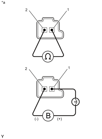
*a Component without harness connected
(Solenoid (SLT) Valve)
Remove the solenoid (SLT) valve.
for 2WD:
for AWD:
-
Measure the resistance according to the value(s) in the table below.
Standard Resistance Tester Connection Condition Specified Condition Terminal 1 of the solenoid (SLT) valve - terminal 2 20°C (68°F) 5.0 to 5.6 Ω -
Connect a positive (+) lead from the battery with a 21 W bulb to terminal 1 and a negative (-) lead to terminal 2 of the solenoid valve connector. Check that the valve moves and makes an operating sound.
OK Valve moves and makes an operating sound. -
Install the solenoid (SLT) valve.
Result Proceed to OK NG
- OKClick here
- NG
REPLACE SOLENOID (SLT) VALVE for 2WD:
REPLACE SOLENOID (SLT) VALVEClick here
REPLACE SOLENOID (SLT) VALVE for AWD:
REPLACE SOLENOID (SLT) VALVEClick here
-
- Click here
INSPECT TRANSMISSION VALVE BODY ASSEMBLY
-
Check the transmission valve body assembly.
for 2WD:
for AWD:
OK There is no foreign matter on each valve and they operate smoothly. Result Proceed to OK NG
- OK
SOLENOID VALVE CIRCUIT NORMAL (PERFORM NEXT STEP FOR REFERENCED DTC)
- NG
REPAIR OR REPLACE TRANSMISSION VALVE BODY ASSEMBLY for 2WD:
REPAIR OR REPLACE TRANSMISSION VALVE BODY ASSEMBLYClick here
REPAIR OR REPLACE TRANSMISSION VALVE BODY ASSEMBLY for AWD:
REPAIR OR REPLACE TRANSMISSION VALVE BODY ASSEMBLYClick here
-