HYBRID CONTROL SYSTEM, Diagnostic DTC:P071015
| DTC Code | DTC Name |
|---|---|
| P071015 | Transmission Fluid Temperature Sensor "A" Circuit Short to Battery or Open |
DTC SUMMARY
-
MALFUNCTION DESCRIPTION
This DTC indicates that the AD value (ECU recognition voltage value) of the fluid temperature sensor installed in the transmission fluid pressure control circuit is abnormal. The cause of this malfunction may be one of the following:
-
Open or short between fluid temperature sensor and hybrid vehicle control ECU assembly
-
Fluid temperature sensor malfunction
-
DESCRIPTION
The ATF temperature sensor converts the automatic transmission fluid (ATF) temperature into a resistance value for use by the hybrid vehicle control ECU assembly.
| DTC No. | Detection Item | DTC Detection Condition | Trouble Area | MIL | Warning Indicate |
|---|---|---|---|---|---|
| P071015 | Transmission Fluid Temperature Sensor "A" Circuit Short to Battery or Open | When P071011 is not stored, ATF temperature sensor voltage (AD value) is higher than 4.9 V for 3 seconds or more (1-trip detection logic) |
|
Comes on | Master Warning Light: Comes on |
| DTC No. | Data List |
|---|---|
| P071015 | Transmission Fluid Temperature* |
*: -39°C (-38.2°F) or higher and less than 214°C (417.2°F) when normal
Standard:
Power switch on (IG) while engine is cold: Same as ambient air temperature
After stall test: 50°C (122°F) to 100°C (212°F)
CONFIRMATION DRIVING PATTERN
Tech Tips
After repair has been completed, clear the DTC and then check that the vehicle has returned to normal by performing the following All Readiness check procedure.
-
Connect the GTS to the DLC3.
-
Turn the power switch on (IG) and turn the GTS on.
-
Clear the DTCs (even if no DTCs are stored, perform the clear DTC procedure).
-
Turn the power switch off and wait for 2 minutes or more.
-
Turn the power switch on (READY) and wait for 5 seconds or more.*1
-
Enter the following menus: Powertrain / Hybrid Control / Utility / All Readiness.
-
Check the DTC judgment result.
Tech Tips
-
If the judgment result shows NORMAL, the system is normal.
-
If the judgment result shows ABNORMAL, the system has a malfunction.
-
If the judgment result shows INCOMPLETE, perform driving pattern again.
-
PROCEDURE
-
CHECK HARNESS AND CONNECTOR (ATF TEMPERATURE SENSOR - HYBRID VEHICLE CONTROL ECU ASSEMBLY)
-
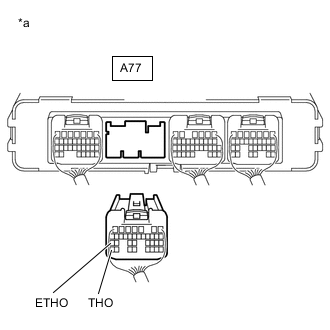
*a Rear view of wire harness connector
(to Hybrid Vehicle Control ECU Assembly)
Disconnect the A77 hybrid vehicle control ECU assembly connector.
-
Measure the resistance according to the value(s) in the table below.
Standard Resistance Tester Connection Condition Specified Condition A77-35 (THO) - A77-27 (ETHO) ATF Temperature 10°C (50°F) 5 to 8 kΩ A77-35 (THO) - A77-27 (ETHO) ATF Temperature 25°C (77°F) 2.5 to 4.5 kΩ A77-35 (THO) - A77-27 (ETHO) ATF Temperature 110°C (230°F) 0.22 to 0.28 kΩ Tech Tips
The resistance value for the 25°C (77°F) ATF temperature condition is a reference value.
-
Measure the resistance according to the value(s) in the table below.
Standard Resistance Tester Connection Condition Specified Condition A77-27 (ETHO) - Body ground and other terminals Power switch off 10 kΩ or higher A77-35 (THO) - Body ground and other terminals Power switch off 10 kΩ or higher -
Reconnect the A77 hybrid vehicle control ECU assembly connector.
Result Proceed to OK NG
OK 
REPLACE HYBRID VEHICLE CONTROL ECU ASSEMBLY Click here
NG 
-
-
CHECK HARNESS AND CONNECTOR (TRANSMISSION WIRE - HYBRID VEHICLE CONTROL ECU ASSEMBLY)
-
Disconnect the D8 transmission wire connector.
-
Disconnect the A77 hybrid vehicle control ECU assembly connector.
-
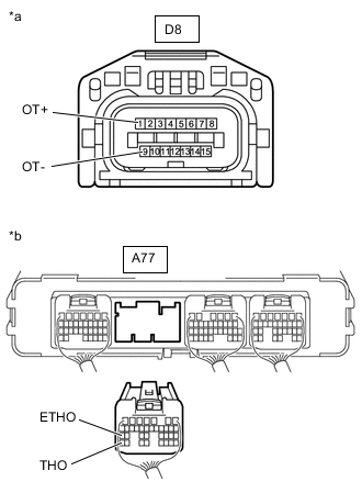
*a Front view of wire harness connector
(to Transmission Wire)
*b Rear view of wire harness connector
(to Hybrid Vehicle Control ECU Assembly)
Measure the resistance according to the value(s) in the table below.
Standard Resistance Tester Connection Condition Specified Condition D8-1 (OT+) - A77-35 (THO) Power switch off Below 1 Ω D8-9 (OT-) - A77-27 (ETHO) Power switch off Below 1 Ω D8-1 (OT+) or A77-35 (THO) - Other terminals Power switch off 10 kΩ or higher D8-9 (OT-) or A77-27 (ETHO) - Other terminals Power switch off 10 kΩ or higher -
Reconnect the A77 hybrid vehicle control ECU assembly connector.
-
Reconnect the D8 transmission wire connector.
Result Proceed to OK NG
OK
REPAIR OR REPLACE TRANSMISSION WIRE (ATF TEMPERATURE SENSOR) for 2WD: REPAIR OR REPLACE TRANSMISSION WIRE (ATF TEMPERATURE SENSOR) Click here
REPAIR OR REPLACE TRANSMISSION WIRE (ATF TEMPERATURE SENSOR) for AWD: REPAIR OR REPLACE TRANSMISSION WIRE (ATF TEMPERATURE SENSOR) Click hereNG
REPAIR OR REPLACE HARNESS OR CONNECTOR (TRANSMISSION WIRE - HYBRID VEHICLE CONTROL ECU ASSEMBLY)
-