HYBRID CONTROL SYSTEM TERMINALS OF ECU
-
HYBRID VEHICLE CONTROL ECU ASSEMBLY
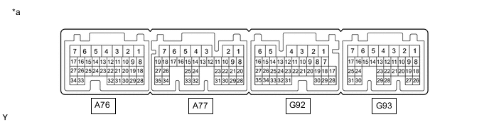
*a Hybrid Vehicle Control ECU Assembly - - Terminal No.
(Symbol)
Wiring Color Input/Output Terminal Description Condition Specified Condition A76-1 (TPM2) - G92-6 (E1) B - W-B OUT Oil pump motor Power switch on (IG) 11 to 14 V A76-3 (SC1) - G92-6 (E1) R - W-B IN SC1 solenoid valve signal Shift state in park (P) or neutral (N) 11 to 14 V Engine brake operating with shift state in manual (M) (1st gear selected) 11 to 14 V A76-11 (SC2) - G92-6 (E1) G - W-B IN SC2 solenoid valve signal Shift state in reverse (R) 11 to 14 V A76-12 (LIN3) - G92-6 (E1) V - W-B IN/OUT LIN communication signal
(A/C inverter, auxiliary battery)
Power switch on (READY) Pulse generation A76-19 (VCPA) - A76-18 (EPA) P - W OUT Accelerator pedal sensor assembly power source (for VPA) Power switch on (IG) 4.5 to 5.5 V A76-20 (VPA2) - A76-29 (EPA2) G - L IN Accelerator pedal sensor assembly (for accelerator pedal sensor malfunction detection) Power switch on (IG), accelerator pedal released 1.0 to 2.2 V Power switch on (IG), engine stopped, shift state in park (P), accelerator pedal fully depressed 3.4 to 5.3 V A76-28 (VPA) - A76-18 (EPA) V - W IN Accelerator pedal sensor assembly (for accelerator pedal position detection) Power switch on (IG), accelerator pedal released 0.4 to 1.4 V Power switch on (IG), engine stopped, shift state in park (P), accelerator pedal fully depressed 2.6 to 4.5 V A76-30 (VCP2) - A76-29 (EPA2) Y - L OUT Accelerator pedal sensor assembly power source (for VPA2) Power switch on (IG) 4.5 to 5.5 V A76-32 (GMT) - A76-21 (GMTG) G - GR IN Generator temperature sensor Power switch on (IG), temperature 25°C (77°F) 3.6 to 4.6 V Power switch on (IG), temperature 60°C (140°F) 2.2 to 3.2 V A76-33 (TPM1) - G92-6 (E1) LG - W-B OUT Oil pump motor Power switch on (READY) Pulse generation
(Waveform 1)
A76-34 (TPST) - G92-6 (E1) B - W-B IN Oil pump motor Power switch on (READY) Pulse generation
(Waveform 2)
A77-1 (MREL) - G92-6 (E1) G*1 - W-B
LG*2 - W-B
OUT Main relay Power switch on (IG) 11 to 14 V A77-2 (IG2) - G92-6 (E1) B - W-B IN Power source Power switch on (IG) 11 to 14 V A77-5 (SL2+) - A77-4 (SL2-) SB - GR OUT SL2 solenoid valve signal During Active Test Pulse generation
(Waveform 3)
A77-7 (SL1+) - A77-6 (SL1-) W - P OUT SL1 solenoid valve signal During Active Test Pulse generation
(Waveform 4)
A77-8 (STP) - G92-6 (E1) R - W-B IN Stop light switch Brake pedal depressed 11 to 14 V Brake pedal released 0 to 1.5 V A77-9 (IWP) - G92-6 (E1) R - W-B OUT Inverter water pump assembly signal Power switch on (READY) Pulse generation
(Waveform 5)
A77-10 (NIWP) - G92-6 (E1) LA-G - W-B IN Inverter water pump assembly signal Power switch on (READY) Pulse generation
(Waveform 5)
A77-11 (IDH) - G92-6 (E1) G - W-B OUT PTC heater prohibit signal Power switch on (IG) 0 to 2.0 V A77-13 (SLT+) - A77-12 (SLT-) G - L - SLT solenoid valve signal Engine idling Pulse generation
(Waveform 6)
A77-14 (NODD) - G92-6 (E1) W - W-B IN/OUT DC/DC operation DC/DC converter operating normally 5 to 7 V DC/DC converter not operating normally 2 to 4 V DC/DC converter operation prohibited 0.1 to 0.5 V A77-15 (VLO) - G92-6 (E1) R - W-B OUT DC/DC operation monitor/voltage change signal Power switch on (IG) Pulse generation
(Waveform 7)
A77-17 (SL4+) - A77-16 (SL4-) R - LG OUT SL4 solenoid valve signal During Active Test Pulse generation
(Waveform 8)
A77-19 (SL3+) - A77-18 (SL3-) V- B OUT SL3 solenoid valve signal During Active Test Pulse generation
(Waveform 9)
A77-20 (HMCL) - G92-6 (E1) R - W-B IN/OUT CAN communication signal
(MG communication)
Power switch on (IG) Pulse generation
(Waveform 10)
A77-21 (ST1-) - G92-6 (E1) B - W-B IN Brake cancel switch Power switch on (IG), brake pedal depressed 0 to 1.5 V Power switch on (IG), brake pedal released 11 to 14 V A77-23 (MMT) - A77-22 (MMTG) L - R IN Motor temperature sensor Power switch on (IG), temperature 25°C (77°F) 3.6 to 4.6 V Power switch on (IG), temperature 60°C (140°F) 2.2 to 3.2 V A77-25 (HSDN) - G92-6 (E1) B - W-B OUT MG ECU shutdown signal Power switch on (READY) 0 to 1.5 V A77-28 (HMCH) - G92-6 (E1) G - W-B IN/OUT CAN communication signal
(MG communication)
Power switch on (IG) Pulse generation
(Waveform 10)
A77-30 (TOPM) - A77-31 (ETOP) L - P IN Oil pump motor temperature sensor Power switch on (IG), temperature 25°C (77°F) 3.5 to 4.2 V A77-32 (SP2O) - G92-6 (E1) W - W-B IN Transmission revolution sensor signal Driving at approximately 20 km/h (12 mph) Pulse generation
(Waveform 11)
A77-33 (SP2B) - G92-6 (E1) B - W-B - Transmission revolution sensor signal Power switch on (IG), engine stopped 11 to 14 V A77-35 (THO) - A77-27 (ETHO) Y - L IN Transmission fluid temperature sensor Power switch on (IG), temperature 25°C (77°F) 2.2 to 2.8 V G92-1 (SMRG) - A76-2 (E01) L - W-B OUT System main relay operation signal Power switch on (IG)→Power switch on (READY) Pulse generation
(Waveform 12)
G92-4 (+B1) - G92-6 (E1) P - W-B IN Power source Power switch on (IG) 11 to 14 V G92-5 (SMRB) - A76-2 (E01) W - W-B OUT System main relay operation signal Power switch on (IG)→Power switch on (READY) Pulse generation
(Waveform 12)
G92-8 (KOK) - G92-6 (E1) R - W-B OUT Proximity sound permission signal Power switch on (IG) 0 to 2.0 V G92-9 (ST2) - G92-6 (E1) V - W-B IN Starter signal Power switch on (IG) 0 to 1.5 V G92-10 (NORM) - G92-6 (E1) G - W-B IN Normal mode switch (satellite switch set) signal Power switch on (IG), normal mode switch (satellite switch set) not operated 11 to 14 V Power switch on (IG), normal mode switch (satellite switch set) operated 0 to 1.5 V G92-15 (SMRP) - A76-2 (E01) GR - W-B OUT System main relay operation signal Power switch on (IG)→Power switch on (READY) Pulse generation
(Waveform 12)
G92-16 (SPRT) - G92-6 (E1) B - W-B IN Sport mode switch (satellite switch set) signal Power switch on (IG), sport mode switch (satellite switch set) not operated 11 to 14 V Power switch on (IG), sport mode switch (satellite switch set) operated 0 to 1.5 V G92-25 (SBFS) - G92-6 (E1) BE - W-B IN Electronic shift lever system fail-safe signal Power switch on (IG) Pulse generation
(Waveform 16)
G92-34 (CA4H) - G92-6 (E1) P - W-B IN/OUT CAN communication signal Power switch on (IG) Pulse generation
(Waveform 13)
G92-35 (CA4L) - G92-6 (E1) W - W-B IN/OUT CAN communication signal Power switch on (IG) Pulse generation
(Waveform 13)
G93-1 (BATT) - G92-6 (E1) V - W-B IN Constant power source Always 11 to 14 V G93-3 (+B2) - G92-6 (E1) L - W-B IN Power source Power switch on (IG) 11 to 14 V G93-4 (IGB) - G92-6 (E1) LG - W-B IN Power source Power switch on (IG) 11 to 14 V G93-8 (SFTD) - G92-6 (E1) B - W-B IN Transmission control Power switch on (IG), shift paddle switch LH (-) not operated 11 to 14 V Power switch on (IG), shift paddle switch LH (-) operated 0 to 1.5 V G93-15 (EVSW) - G92-6 (E1) B - W-B IN EV mode switch (integration control & panel assembly) signal Power switch on (IG), EV mode switch (integration control & panel assembly) not operated 11 to 14 V Power switch on (IG), EV mode switch (integration control & panel assembly)operated 0 to 1.5 V G93-16 (TC) - G92-6 (E1) GR - W-B IN Diagnosis terminal Power switch on (IG) 11 to 14 V G93-18 (SFTU) - G92-6 (E1) Y - W-B IN Transmission control Power switch on (IG), shift paddle switch RH (+) not operated 11 to 14 V Power switch on (IG), shift paddle switch RH (+) operated 0 to 1.5 V G93-20 (ILK) - G92-6 (E1) G - W-B IN Interlock switch signal Power switch on (IG), service plug grip installed correctly 0 to 1.5 V Power switch on (IG), service plug grip not installed 11 to 14 V G93-24 (CA1L) - G92-6 (E1) W - W-B IN/OUT CAN communication signal Power switch on (IG) Pulse generation
(Waveform 14)
G93-25 (CA1H) - G92-6 (E1) L - W-B IN/OUT CAN communication signal Power switch on (IG) Pulse generation
(Waveform 14)
G93-27 (SNOW) - G92-6 (E1) LG - W-B IN Snow mode switch (No. 2 satellite switch set) signal Power switch on (IG), snow mode switch (No. 2 satellite switch set) not operated 11 to 14 V Power switch on (IG), snow mode switch (No. 2 satellite switch set) operated 0 to 1.5 V G93-30 (CA3N) - G92-6 (E1) W - W-B IN/OUT CAN communication signal Power switch on (IG) Pulse generation
(Waveform 15)
G93-31 (CA3P) - G92-6 (E1) SB - W-B IN/OUT CAN communication signal Power switch on (IG) Pulse generation
(Waveform 15)
*1: for LHD
*2: for RHD
-
Oscilloscope waveforms
Tech Tips
Oscilloscope waveform samples are provided here for informational purposes. Noise and fluttering waveforms have been omitted.
-
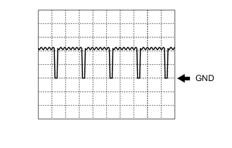
Waveform 1 (Oil pump motor signal)
Item Content Terminal A76-33 (TPM1) - G92-6 (E1) Equipment Setting 5 V/DIV., 500 μs./DIV. Condition Power switch on (READY) -
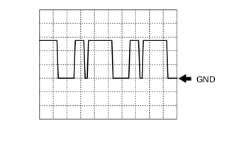
Waveform 2 (Oil pump motor signal)
Item Content Terminal A76-34 (TPST) - G92-6 (E1) Equipment Setting 5 V/DIV., 5 ms./DIV. Condition Power switch on (READY) -
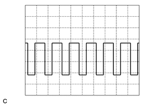
Waveform 3 (SL2 solenoid valve signal)
Item Content Terminal A77-5 (SL2+) - A77-4 (SL2-) Equipment Setting 5 V/DIV., 2 ms./DIV. Condition During Active Test -
Waveform 4 (SL1 solenoid valve signal)
Item Content Terminal A77-7 (SL1+) - A77-6 (SL1-) Equipment Setting 5 V/DIV., 2 ms./DIV. Condition During Active Test -
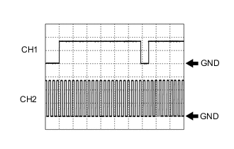
Waveform 5 (Inverter water pump assembly signal)
Item Content Terminal CH1: A77-9 (IWP) - G92-6 (E1)
CH2: A77-10 (NIWP) - G92-6 (E1)
Equipment Setting 5 V/DIV., 20 ms./DIV. Condition Power switch on (READY) -
Waveform 6 (SLT solenoid valve signal)
Item Content Terminal A77-13 (SLT+) - A77-12 (SLT-) Equipment Setting 5 V/DIV., 2 ms./DIV. Condition Engine idling -
Waveform 7 (DC/DC operation monitor/voltage change signal)
Item Content Terminal A77-15 (VLO) - G92-6 (E1) Equipment Setting 5 V/DIV., 50 ms./DIV. Condition Power switch on (IG) Tech Tips
The cycle will vary depending on the specified voltage of the hybrid vehicle converter.
-
Waveform 8 (SL4 solenoid valve signal)
Item Content Terminal A77-17 (SL4+) - A77-16 (SL4-) Equipment Setting 5 V/DIV., 2 ms./DIV. Condition During Active Test -
Waveform 9 (SL3 solenoid valve signal)
Item Content Terminal A77-19 (SL3+) - A77-18 (SL3-) Equipment Setting 5 V/DIV., 2 ms./DIV. Condition During Active Test -
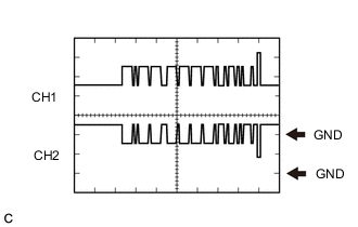
Waveform 10 (CAN communication signal)
Item Content Terminal CH1: A77-28 (HMCH) - G92-6 (E1)
CH2: A77-20 (HMCL) - G92-6 (E1)
Equipment Setting 1 V/DIV., 50 μs./DIV. Condition Power switch on (IG) Tech Tips
The waveform will vary depending on the content of the digital communication (digital signal).
-
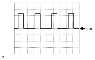
Waveform 11 (Output shaft speed signal)
Item Content Terminal A77-32 (SP2O) - G92-6 (E1) Equipment Setting 5 V/DIV., 2 ms./DIV. Condition Driving at approximately 20 km/h (12 mph) Tech Tips
The higher the vehicle speed, the shorter the cycle.
-
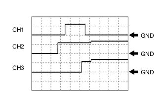
Waveform 12 (System main relay operation signal)
Item Content Terminal CH1: G92-15 (SMRP) - A76-2 (E01)
CH2: G92-5 (SMRB) - A76-2 (E01)
CH3: G92-1 (SMRG) - A76-2 (E01)
Equipment Setting 10 V/DIV., 200 ms./DIV. Condition Power switch on (IG)→Power switch on (READY) Tech Tips
The waveform will vary depending on the content of the digital communication (digital signal).
-
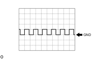
Waveform 13 (CAN communication signal)
Item Content Terminal CH1: G92-34 (CA4H) - G92-6 (E1)
CH2: G92-35 (CA4L) - G92-6 (E1)
Equipment Setting 1 V/DIV., 50 μs./DIV. Condition Power switch on (IG) Tech Tips
The waveform will vary depending on the content of the digital communication (digital signal).
-
Waveform 14 (CAN communication signal)
Item Content Terminal CH1: G93-25 (CA1H) - G92-6 (E1)
CH2: G93-24 (CA1L) - G92-6 (E1)
Equipment Setting 1 V/DIV., 50 μs./DIV. Condition Power switch on (IG) Tech Tips
The waveform will vary depending on the content of the digital communication (digital signal).
-
Waveform 15 (CAN communication signal)
Item Content Terminal CH1: G93-31 (CA3P) - G92-6 (E1)
CH2: G93-30 (CA3N) - G92-6 (E1)
Equipment Setting 1 V/DIV., 50 μs./DIV. Condition Power switch on (IG) Tech Tips
The waveform will vary depending on the content of the digital communication (digital signal).
-
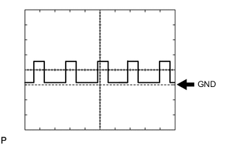
Waveform 16 (Electronic shift lever system fail-safe signal)
Item Content Terminal G92-25 (SBFS) - G92-6 (E1) Equipment Setting 10 V/DIV., 20 ms./DIV. Condition Power switch on (IG) Tech Tips
The waveform will vary depending on the content of the digital communication (digital signal).
-
-