AIR FUEL RATIO SENSOR REMOVAL

CAUTION / NOTICE / HINT
The necessary procedures (adjustment, calibration, initialization or registration) that must be performed after parts are removed and installed, or replaced during air fuel ratio sensor removal/installation are shown below.
| Replaced Part or Performed Procedure | Necessary Procedure | Effect/Inoperative Function when Necessary Procedure not Performed | Link |
|---|---|---|---|
|
Inspection after repair |
|
|
PROCEDURE
-
REMOVE V-BANK COVER SUB-ASSEMBLY
-
REMOVE RADIATOR COVER PLATE
-
REMOVE UPPER RADIATOR SUPPORT SEAL
-
REMOVE LOWER RADIATOR AIR DEFLECTOR
-
REMOVE FENDER APRON BRACE SUB-ASSEMBLY LH (for RHD)
-
REMOVE INVERTER MOTOR CABLE BRACKET ASSEMBLY (for RHD)
-
REMOVE FENDER APRON BRACE SUB-ASSEMBLY RH (for LHD)
-
REMOVE INVERTER MOTOR CABLE BRACKET ASSEMBLY (for LHD)
-
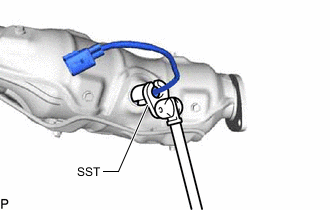
REMOVE AIR FUEL RATIO SENSOR (for Bank 1 Sensor 1)
-
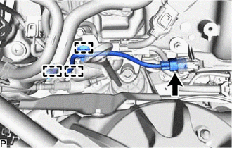
Disconnect the air fuel ratio sensor connector.
-
Detach the 3 wire harness clamps.
-
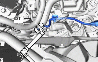
Using SST, remove the air fuel ratio sensor from the exhaust manifold assembly RH.
- SST
- 09224-00012
-
-
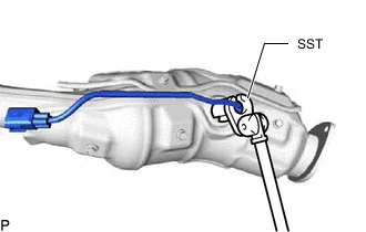
REMOVE AIR FUEL RATIO SENSOR (for Bank 2 Sensor 1)
-
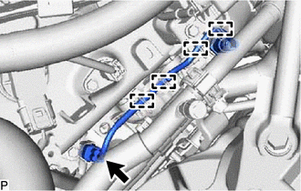
Disconnect the air fuel ratio sensor connector.
-
Detach the 4 wire harness clamps.
-
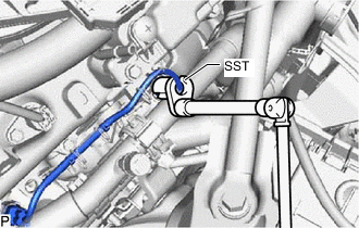
Using SST, remove the air fuel ratio sensor from the exhaust manifold assembly LH.
- SST
- 09224-00012
-
-
REMOVE EXHAUST MANIFOLD ASSEMBLY RH
-
REMOVE EXHAUST MANIFOLD ASSEMBLY LH
-
REMOVE AIR FUEL RATIO SENSOR (for Bank 1 Sensor 2)
-
Using SST, remove the air fuel ratio sensor from the exhaust manifold assembly RH.
- SST
- 09224-00012
-
-
REMOVE AIR FUEL RATIO SENSOR (for Bank 2 Sensor 2)
-
Using SST, remove the air fuel ratio sensor from the exhaust manifold assembly LH.
- SST
- 09224-00012
-