RELAY ON-VEHICLE INSPECTION
PROCEDURE
-
INSPECT NO. 1 ELECTRONIC FUEL INJECTION MAIN RELAY (EFI-MAIN NO. 1)
-
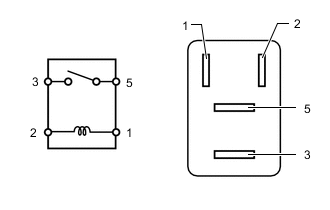
Measure the resistance according to the value(s) in the table below.
Standard Resistance Tester Connection Condition Specified Condition 3 - 5 Battery voltage not applied between terminals 1 and 2 10 kΩ or higher Battery voltage applied between terminals 1 and 2 Below 1 Ω
-
-
INSPECT NO. 2 ELECTRONIC FUEL INJECTION MAIN RELAY (EFI-MAIN NO. 2)
-
Measure the resistance according to the value(s) in the table below.
Standard Resistance Tester Connection Condition Specified Condition 3 - 5 Battery voltage not applied between terminals 1 and 2 10 kΩ or higher Battery voltage applied between terminals 1 and 2 Below 1 Ω
-
-
INSPECT ELECTRONIC DRIVER UNIT RELAY (EDU RELAY)
-
Measure the resistance according to the value(s) in the table below.
Standard Resistance Tester Connection Condition Specified Condition 3 - 5 Battery voltage not applied between terminals 1 and 2 10 kΩ or higher Battery voltage applied between terminals 1 and 2 Below 1 Ω
-
-
INSPECT AIR FUEL RATIO SENSOR HEATER RELAY (A/F HTR RELAY)
-
Measure the resistance according to the value(s) in the table below.
Standard Resistance Tester Connection Condition Specified Condition 3 - 5 Battery voltage not applied between terminals 1 and 2 10 kΩ or higher Battery voltage applied between terminals 1 and 2 Below 1 Ω
-
-
INSPECT NO. 1 IGNITION RELAY (IG1)
-
Measure the resistance according to the value(s) in the table below.
Standard Resistance Tester Connection Condition Specified Condition 3 - 5 Battery voltage not applied between terminals 1 and 2 10 kΩ or higher Battery voltage applied between terminals 1 and 2 Below 1 Ω
-
-
INSPECT NO. 2 IGNITION RELAY (IG2 NO. 2)
-
Measure the resistance according to the value(s) in the table below.
Standard Resistance Tester Connection Condition Specified Condition 3 - 5 Battery voltage not applied between terminals 1 and 2 10 kΩ or higher Battery voltage applied between terminals 1 and 2 Below 1 Ω
-
-
INSPECT DRIVER SIDE JUNCTION BLOCK ASSEMBLY (IG2 D RELAY)
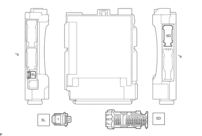
*a Component without harness connected
(Driver Side Junction Block Assembly)
- - Note
-
The IG2 D relay are built into the driver side junction block assembly.
-
Before performing the relay inspections for the relays of the driver side junction block assembly, inspect the IG2 D NO. 3 fuse.
-
Remove the driver side junction block assembly.
-
Remove the main body ECU from the driver side junction block assembly.
-
Measure the resistance according to the value(s) in the table below.
Standard Resistance (for LHD) Tester Connection Condition Specified Condition 5L-1 - 5D-26 Battery voltage not applied between terminals 5D-18 and 5D-6 10 kΩ or higher Battery voltage applied between terminals 5D-18 and 5D-6 Below 1 Ω Standard Resistance (for RHD) Tester Connection Condition Specified Condition 5L-1 - 5D-26 Battery voltage not applied between terminals 5D-19 and 5D-7 10 kΩ or higher Battery voltage applied between terminals 5D-19 and 5D-7 Below 1 Ω -
Install the main body ECU to the driver side junction block assembly.
-
Install the driver side junction block assembly.
-