THROTTLE BODY INSTALLATION
CAUTION / NOTICE / HINT
Tech Tips
Perform "Inspection After Repairs" after replacing the throttle body with motor assembly.
-
w/ Canister Pump Module:
-
w/o Canister Pump Module:
PROCEDURE
-
INSTALL THROTTLE BODY WITH MOTOR ASSEMBLY
Tech Tips
Perform "Inspection After Repairs" after replacing the throttle body with motor assembly.
-
w/ Canister Pump Module:
-
w/o Canister Pump Module:
-
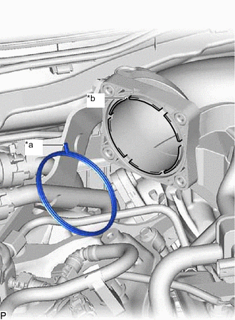
*a Protrusion *b Groove Install a new gasket to the intake air surge tank assembly with the protrusion of the gasket oriented as shown in the illustration.
-
Connect the water by-pass hose to the throttle body with motor assembly and slide the clip to secure the hose.
-
Connect the No. 4 water by-pass hose to the throttle body with motor assembly and slide the clip to secure the hose.
-
Install the throttle body with motor assembly to the intake air surge tank assembly with the 4 bolts.
- Torque:
- 10 N*m { 102 kgf*cm, 7 ft.*lbf }
-
Connect the throttle body with motor assembly connector.
-
-
INSTALL THROTTLE BODY BRACKET
Note
Do not apply oil to the bolts as listed below:
Oil Application Prohibited Bolt Bolt for Intake Air Surge Tank Assembly and Cylinder head cover sub-assembly
-
Install the throttle body bracket with the 2 bolts.
- Torque:
- 21 N*m { 214 kgf*cm, 15 ft.*lbf }
-
-
CONNECT NO. 3 WATER BY-PASS HOSE ASSEMBLY
-
Connect the No. 3 water by-pass hose assembly with the nut.
- Torque:
- 21 N*m { 214 kgf*cm, 15 ft.*lbf }
-
for LHD:
Attach the 4 clamps to connect the motor cable and generator cable.
-
-
INSTALL AIR CLEANER WITH AIR CLEANER HOSE
-
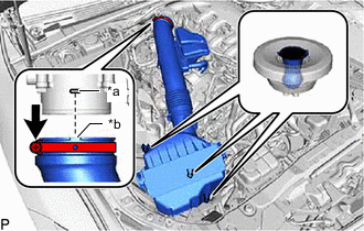
*a Protrusion *b Groove Connect the air cleaner with air cleaner hose to the throttle body with motor assembly.
Note
Fit the protrusion on the air cleaner hose assembly into the hole of the hose clamp on the throttle body with motor assembly side.
-
Insert the 3 air cleaner with air cleaner hose pins into the air cleaner support.
-
Tighten the hose clamp.
- Torque:
- 4.0 N*m { 41 kgf*cm, 35 in.*lbf }
-
Attach the clamp to the air cleaner with air cleaner hose.
-
Attach the wire harness clamp.
-
Connect the mass air flow meter sub-assembly connector.
-
-
INSTALL NO. 1 AIR CLEANER INLET
-
Install the No. 1 air cleaner inlet to the air cleaner with air cleaner hose and insert the pin into the air cleaner support.
-
-
CONNECT NO. 2 PCV HOSE
-
Connect the No. 2 PCV hose to the cylinder head cover sub-assembly and slide the clip to secure the hose.
-
-
ADD ENGINE COOLANT
-
INSPECT FOR COOLANT LEAK
-
INSTALL RADIATOR SUPPORT TO CROSS MEMBER BRACE SUB-ASSEMBLY RH
-
INSTALL LOWER RADIATOR AIR DEFLECTOR
-
INSTALL UPPER RADIATOR SUPPORT SEAL
-
INSTALL RADIATOR COVER PLATE
-
INSTALL V-BANK COVER SUB-ASSEMBLY