PROCEDURE
- Click here
INSTALL DIFFERENTIAL RING GEAR
-
Clean the contact surfaces of the rear differential case sub-assembly and differential ring gear.
-
Clean the ring gear set bolt hole.
-
Heat the differential ring gear to approximately 100°C (212°F) in boiling water.
-
Carefully take the differential ring gear out of the boiling water.
CAUTION:Use thick gloves to protect your hands as the differential ring gear is hot.
-
Secure the rear differential case sub-assembly between aluminum plates in a vise.
Note:Do not overtighten the vise.
-
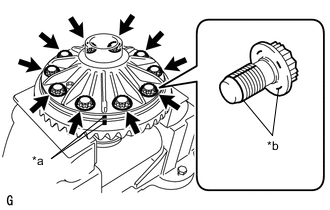
*a Matchmark *b Thread Lock After the moisture on the differential ring gear has completely evaporated, quickly install the differential ring gear to the rear differential case sub-assembly.
-
Align the matchmarks on the differential ring gear and rear differential case sub-assembly.
-
After the differential ring gear has cooled sufficiently, install 10 new bolts to which thread lock has been applied.
Adhesive Toyota Genuine Adhesive 1360K, Three Bond 1360K or equivalent. Note:
-
New ring gear set bolts should be used every time the differential ring gear is installed.
-
Do not allow oil to adhere to the ring gear set bolts during installation.
-
-
Temporarily install the 10 bolts.
-
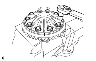
After the differential ring gear cools down, tighten the 10 bolts.
63.7 N*m 650 kgf*cm 47 ft.*lbf Note:Tighten diametrically opposite ring gear set bolts in pairs.
-
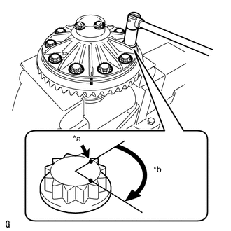
*a Paint Mark *b 60° to 90° Tighten the 12 set bolts an additional 60° to 90°.
Note:Tighten diametrically opposite ring gear set bolts in pairs.
-
- Click here
INSTALL REAR DIFFERENTIAL CASE BEARING
-
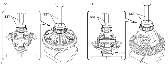
*A for LH Side *B for RH Side Using SST and a press, install the rear differential case bearing (inner races) LH and RH to the rear differential case sub-assembly.
09550-60010 09951-00560 09951-00570 09950-70010 09951-07100 Note:
-
Do not apply hypoid gear oil to a new bearing.
-
Do not deform the bearing cage. Set SST to the center of the rear differential case sub-assembly.
-
If the bearing is replaced, replace it and its outer race as a set.
-
-
- Click here
INSTALL REAR DRIVE PINION REAR BEARING
-
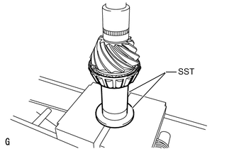
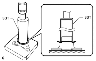
Using SST and a press, install the rear drive pinion rear bearing (inner race) to the differential drive pinion.
09316-60012 09316-00031 09612-24014 09613-22011 Note:Do not apply hypoid gear oil to a new bearing.
Tip:Disassemble SST (09613-22011) and use only the pipe section.
-
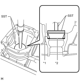
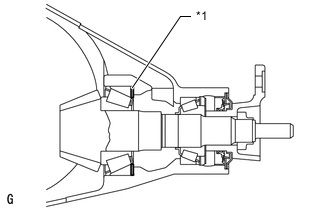
*1 Rear Drive Pinion Rear Bearing (Outer Race) *2 Rear Differential Drive Pinion Plate Washer Using SST and a press, install a new rear differential drive pinion plate washer and rear drive pinion rear tapered roller bearing outer race.
09255-10012 09950-70010 09951-07200 Note:Do not apply hypoid gear oil to a new bearing.
Tip:Select a rear differential drive pinion plate washer of the same thickness as the removed one.
-
- Click here
INSTALL REAR DRIVE PINION FRONT BEARING
-
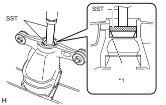
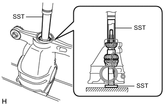
*1 Rear Drive Pinion Front Bearing (Outer Race) Using SST and a press, install the rear drive pinion front bearing (outer race).
09950-60020 09951-00710 09950-70010 09951-07100 Note:Do not apply hypoid gear oil to a new bearing.
-
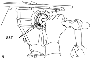
Install the rear drive pinion front bearing (inner race) to the rear differential carrier.
Note:Do not apply hypoid gear oil to a new bearing.
-
- Click here
INSTALL REAR DIFFERENTIAL DUST DEFLECTOR
Tip:Perform this procedure only when replacing the rear differential dust deflector.
-
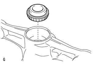
Using SST and a press, insert a new rear differential dust deflector to the rear drive pinion companion flange.
09316-60012 09316-00011 Note:
-
Slowly press in the rear differential dust deflector. Do not press it excessively.
-
If any burrs remain after pressing in the rear differential dust deflector, remove them.
-
-
- Click here
INSTALL DIFFERENTIAL DRIVE PINION
-
Using SST and a press, install the differential drive pinion.
09316-60012 09316-00011 09316-00041 09608-04031 Tip:Install the rear differential drive pinion bearing spacer and rear differential carrier oil seal after adjusting the tooth contact pattern.
-
- Click here
INSTALL REAR DIFFERENTIAL DRIVE PINION OIL SLINGER
-
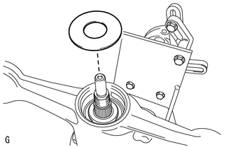
Install the rear differential drive pinion oil slinger.
-
- Click here
INSTALL REAR DRIVE PINION COMPANION FLANGE SUB-ASSEMBLY
-
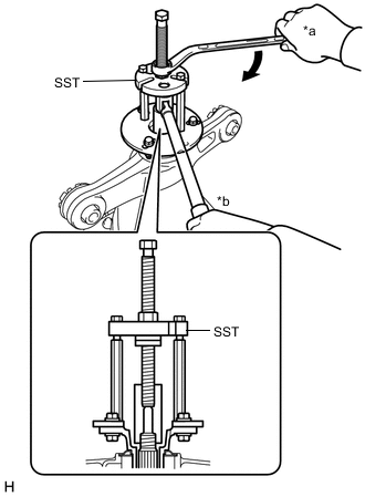
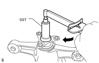
*a Turn *b Hold Using SST, install the rear drive pinion companion flange.
09950-30012 09951-03010 09953-03010 09954-03010 09955-03040 09956-03060 Note:
-
Install the rear drive pinion companion flange so that there is a slight looseness in the differential drive pinion because the rear differential drive pinion bearing spacer is not yet installed.
-
Apply molybdenum grease to the threads of the SST center bolt (09953-03010) before use.
Tip:When securing SST and the companion flange, it is recommended to use M8 X P 1.25 bolts with a length of approximately 40 mm.
-
-
Coat the threads of the rear drive pinion nut with hypoid gear oil LSD.
-
*a Turn *b Hold Using SST and a torque wrench, hold the rear drive pinion companion flange and temporary install the rear drive pinion nut.
09229-55010 09330-00021 09950-30012 09955-03040 490 N*m 4997 kgf*cm 361 ft.*lbf or less CAUTION:Hold the overhaul attachment during the operation.
Note:
-
Apply hypoid gear oil LSD to the rear drive pinion nut and the threads of the differential drive pinion.
-
As there is no rear differential drive pinion bearing spacer, tighten the rear drive pinion nut a little at a time. Do not overtighten it.
Tip:Tighten the nut approximately 100 N*m (1020 kgf*cm, 74 ft.*lbf), and tighten it further while checking the preload.
-
-
- Click here
ADJUST DIFFERENTIAL DRIVE PINION PRELOAD
-
Turn the bearing clockwise and counterclockwise several times to stabilize it.
-

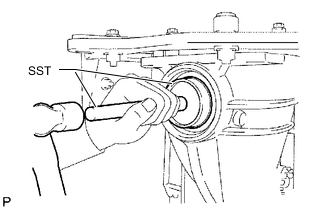
Using SST and a torque wrench, measure the preload.
09229-55010 Differential drive pinion preload (at starting) Item Specified Condition New bearing 1.07 to 1.47 N*m (11.0 to 14.9 kgf*cm, 9.5 to 13.0 in.*lbf) Reused bearing 1.07 to 1.47 N*m (11.0 to 14.9 kgf*cm, 9.5 to 13.0 in.*lbf)
-
If the preload is less than the specified minimum value, check the preload while retightening the drive pinion nut by 5 to 10° to adjust it into the specified range.
Torque 550 N*m (5608 kgf*cm, 406 ft.*lbf) or less
-
-
- Click here
INSTALL REAR DIFFERENTIAL CASE SUB-ASSEMBLY
-

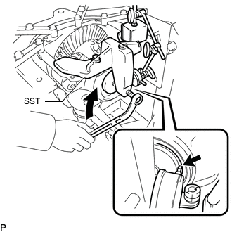
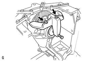
Insert the rear differential case sub-assembly from the differential ring gear tooth side to install the rear differential case sub-assembly as shown in the illustration.
Note:Do not damage the rear differential case bearing or differential ring gear.
-
- Click here
INSTALL REAR DIFFERENTIAL CASE BEARING
-
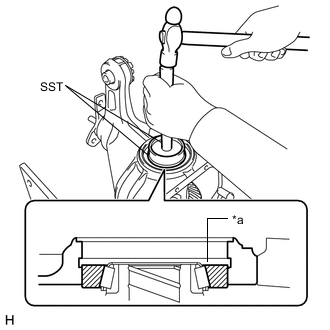
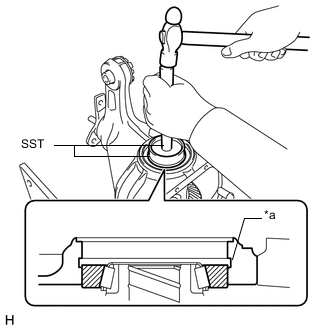
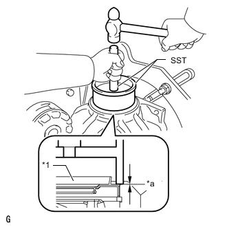
*a Groove Using SST and a hammer, install the differential side bearing (outer race) RH to the differential ring gear tooth side.
09608-32010 09950-70010 09951-07200 Note:Do not apply hypoid gear oil to a new bearing.
Tip:Tap in the rear differential case bearing (outer race) RH until half of the rear differential side gear shaft snap ring groove of the rear differential carrier can be seen.
-
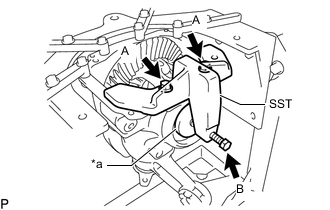
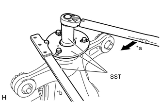
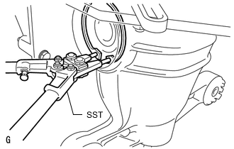
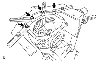
*a Disc Install SST to the differential carrier with the 2 bolts (A) so that the center of the SST disc is at the center of the rear differential case bearing (outer race).
09571-10200 09571-01210 09571-01230 -
Tighten the SST bolt (B) until the SST disc lightly touches the rear differential case bearing (outer race) RH.
-
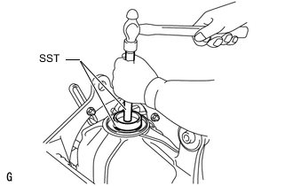
Using SST and a hammer, install the rear differential case bearing (outer race) LH to the differential ring gear back surface side.
09608-32010 09950-70010 09951-07200 Note:Do not apply hypoid gear oil to a new bearing.
Tip:Tap in the rear differential case bearing (outer race) LH until it touches the rear differential case bearing inner race roller.
-
- Click here
INSTALL REAR DIFFERENTIAL SIDE GEAR SHAFT SNAP RING
-

Using SST, install the thinnest rear differential side gear shaft snap ring to the back surface of the differential ring gear.
09905-00031 Tip:
-
If the final gear set (differential drive pinion and differential ring gear) and rear differential case bearing are new, select a thinner rear differential side gear shaft snap ring and install it.
-
If the final gear set (differential drive pinion and differential ring gear) and rear differential case bearing are reused, install a rear differential side gear shaft snap ring with the same thickness as the removed one.
-
-
Install a dial indicator to the rear differential carrier.
Tip:Set the dial indicator as shown in the illustration.
-
Tighten the SST bolt to alter the shape of the rear differential carrier by approximately 0.1 mm (0.00394 in.).
09571-10200 09571-01210 09571-01230 Note:Observe the dial indicator to ensure that the shape of the rear differential carrier does not change by more than 0.2 mm (0.00787 in.).
Tip:Tighten the SST bolt to apply the preload to the rear differential case bearing.
-
Turn the differential ring gear clockwise and counterclockwise several times.
-
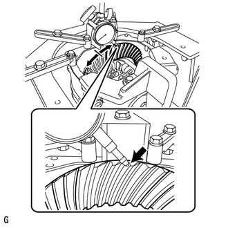
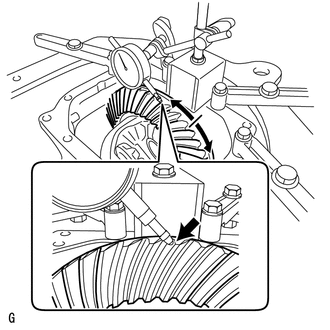
Using a dial indicator, measure the backlash of the differential ring gear at 3 positions.
Backlash 0.08 to 0.13 mm (0.00315 to 0.00511 in.) Note:The difference between the maximum and minimum values must be within 0.05 mm (0.00197 in.).
Tip:
-
Record the measured backlash to use as a reference for selecting a rear differential side gear shaft snap ring.
-
If the backlash is not within the specified range, replace the rear differential side gear shaft snap ring on the differential ring gear tooth side with a rear differential side gear shaft snap ring of a different thickness as described in the following procedure.
-
Inspect the tooth contact and use the result as a reference for selecting a rear differential side gear shaft snap ring.
-
-
Loosen the SST bolt and separate the SST disc from the rear differential case bearing (outer race) RH.
Note:Do not remove SST.
-
Using SST and a hammer, create a clearance between the rear differential side gear shaft snap ring on the differential ring gear back surface side and the rear differential case bearing outer race LH.
09608-32010 09950-70010 09951-07200 -
Using SST, remove the rear differential side gear shaft snap ring from the differential ring gear back surface side.
09905-00031 -
Using SST, install a rear differential side gear shaft snap ring with a different thickness.
09905-00031 Tip:When the rear differential side gear shaft snap ring thickness changes by 0.02 mm (0.000787 in.), the backlash also changes by 0.02 mm (0.000787 in.).
Rear Differential Side Gear Shaft Snap Ring Thickness Part No. No. Thickness Part No. No. Thickness 90521-99062 66 3.6475 to 3.6725 mm (0.1437 to 0.1445 in.) 90521-99084 06 4.0475 to 4.0725 mm (0.1594 to 0.1603 in.) 90521-99063 68 3.6675 to 3.6925 mm (0.1444 to 0.1453 in.) 90521-99085 08 4.0675 to 4.0925 mm (0.1602 to 0.1611 in.) 90521-99064 70 3.6875 to 3.7125 mm (0.1452 to 0.1461 in.) 90521-99086 10 4.0875 to 4.1125 mm (0.1610 to 0.1619 in.) 90521-99065 72 3.7075 to 3.7325 mm (0.1460 to 0.1469 in.) 90521-99087 12 4.1075 to 4.1325 mm (0.1618 to 0.1626 in.) 90521-99066 74 3.7275 to 3.7525 mm (0.1468 to 0.1477 in.) 90521-99088 14 4.1275 to 4.1525 mm (0.1625 to 0.1634 in.) 90521-99067 76 3.7475 to 3.7725 mm (0.1476 to 0.1485 in.) 90521-99089 16 4.1475 to 4.1725 mm (0.1633 to 0.1642 in.) 90521-99068 78 3.7675 to 3.7925 mm (0.1484 to 0.1493 in.) 90521-99090 18 4.1675 to 4.1925 mm (0.1641 to 0.1650 in.) 90521-99070 80 3.7875 to 3.8125 mm (0.1492 to 0.1500 in.) 90521-99091 20 4.1875 to 4.2125 mm (0.1649 to 0.1658 in.) 90521-99071 82 3.8075 to 3.8325 mm (0.1500 to 0.1508 in.) 90521-99092 22 4.2075 to 4.2325 mm (0.1657 to 0.1666 in.) 90521-99072 84 3.8275 to 3.8525 mm (0.1507 to 0.1516 in.) 90521-99095 24 4.2275 to 4.2525 mm (0.1665 to 0.1674 in.) 90521-99073 86 3.8475 to 3.8725 mm (0.1515 to 0.1524 in.) 90521-99096 26 4.2475 to 4.2725 mm (0.1673 to 0.1682 in.) 90521-99074 88 3.8675 to 3.8925 mm (0.1523 to 0.1532 in.) 90521-99097 28 4.2675 to 4.2925 mm (0.1681 to 0.1689 in.) 90521-99075 90 3.8875 to 3.9125 mm (0.1531 to 0.1540 in.) 90521-99100 30 4.2875 to 4.3125 mm (0.1688 to 0.1697 in.) 90521-99076 92 3.9075 to 3.9325 mm (0.1539 to 0.1548 in.) 90521-99101 32 4.3075 to 4.3325 mm (0.1696 to 0.1705 in.) 90521-99077 94 3.9275 to 3.9525 mm (0.1547 to 0.1556 in.) 90521-99102 34 4.3275 to 4.3525 mm (0.1704 to 0.1713 in.) 90521-99078 96 3.9475 to 3.9725 mm (0.1555 to 0.1563 in.) 90521-99103 36 4.3475 to 4.3725 mm (0.1712 to 0.1721 in.) 90521-99079 98 3.9675 to 3.9925 mm (0.1563 to 0.1571 in.) 90521-99104 38 4.3675 to 4.3925 mm (0.1720 to 0.1729 in.) 90521-99081 00 3.9875 to 4.0125 mm (0.1570 to 0.1579 in.) 90521-99105 40 4.3875 to 4.4125 mm (0.1728 to 0.1737 in.) 90521-99082 02 4.0075 to 4.0325 mm (0.1578 to 0.1587 in.) 90521-99107 42 4.4075 to 4.4325 mm (0.1736 to 0.1745 in.) 90521-99083 04 4.0275 to 4.0525 mm (0.1586 to 0.1595 in.) - - - -
Using a plastic-faced hammer, lightly tap the differential ring gear tooth side of the rear differential carrier.
-
Install a dial indicator to the rear differential carrier.
Tip:Set the dial indicator as shown in the illustration.
-
Tighten the SST bolt to alter the shape of the rear differential carrier by approximately 0.1 mm (0.00394 in.).
09571-10200 09571-01220 09571-01230 Note:Observe the dial indicator to ensure that the shape of the rear differential carrier does not change by more than 0.2 mm (0.00787 in.).
-
Using a dial indicator, measure the backlash of the differential ring gear at 3 positions.
Backlash 0.08 to 0.13 mm (0.00315 to 0.00511 in.) If the backlash is not within the specified range, replace the rear differential side gear shaft snap ring on the back surface of the differential ring gear with one of a different thickness.
Tip:
-
Record the measured backlash to use as a reference for selecting a rear differential side gear shaft snap ring.
-
Inspect the tooth contact and use the result as a reference for selecting a rear differential side gear shaft snap ring.
-
-
- Click here
ADJUST REAR DIFFERENTIAL CASE BEARING PRELOAD
-
*a Turn Install a dial indicator to the rear differential carrier.
Tip:Set the dial indicator as shown in the illustration.
-
Tighten the SST bolt to alter the shape of the rear differential carrier by approximately 0.1 mm (0.00394 in.).
09571-10200 09571-01220 09571-01230 Note:Observe the dial indicator to ensure that the shape of the rear differential carrier does not change by more than 0.2 mm (0.00787 in.).
-
Using SST, install the thinnest rear differential side gear shaft snap ring to the differential ring gear tooth side.
09905-00031 -
*a Disc Remove the dial indicator and loosen the bolt until the SST disc is separated from the rear differential case bearing (outer race) RH on the differential ring gear tooth side.
-
Using a plastic-faced hammer, lightly tap the differential ring gear tooth side of the rear differential carrier to stabilize the rear differential case bearing.
-
Using a dial indicator, measure the backlash of the differential ring gear at 3 positions. If even one backlash reading is smaller than the specified value, adjust the differential ring gear backlash by replacing the rear differential side gear shaft snap ring on the differential ring gear tooth side with a thicker one.
Backlash 0.08 to 0.13 mm (0.00315 to 0.00511 in.) Tip:If the value is not within the specified range, replace the snap ring with one of a different thickness in the following procedure.
-
Remove the 2 bolts and SST.
-
- Click here
ADJUST TOTAL PRELOAD
-

Using SST and a torque wrench, measure the preload with the teeth of the differential drive pinion and differential ring gear in contact.
09229-55010 Total Preload (at Starting) Item Specified Condition New bearing 1.57 to 2.86 N*m (16.1 to 29.1 kgf*cm, 13.9 to 25.3 in.*lbf) Reused bearing 1.44 to 2.45 N*m (14.7 to 24.9 kgf*cm, 12.8 to 21.6 in.*lbf) Note:
-
If the measured preload is less than the specified value, replace the rear differential side gear shaft snap ring of the differential ring gear tooth surface side with a thicker one.
-
If the measured preload is more than the specified value, replace the rear differential side gear shaft snap ring of the differential ring gear tooth surface side with a thinner one.
Tip:When the rear differential side gear shaft snap ring thickness changes by 0.02 mm (0.000787 in.), the total preload will change by approximately 0.1 N*m (1 kgf*cm, 1 in.*lbf).
-
-
Set a dial indicator to the end of the differential ring gear face.
-
While holding the rear drive pinion companion flange, rotate the differential ring gear and measure the backlash.
Backlash 0.08 to 0.13 mm (0.00315 to 0.00512 in.) Note:
-
If the measured value is out of the specified range, adjust it by increasing or decreasing the thickness of both the right and left rear differential side gear shaft snap rings equally.
-
When the rear differential side gear shaft snap ring thickness changes by 0.02 mm (0.000787 in.), the backlash will also change by approximately 0.02 mm (0.000787 in.).
-
-
Recheck the total preload.
-
- Click here
INSPECT TOOTH CONTACT BETWEEN RING GEAR AND DRIVE PINION
-
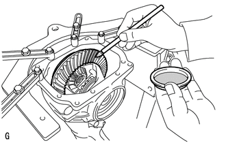
Coat 3 or 4 teeth at 3 different positions on the differential ring gear with Prussian blue.
-
Rotate the differential ring gear in both directions.
-
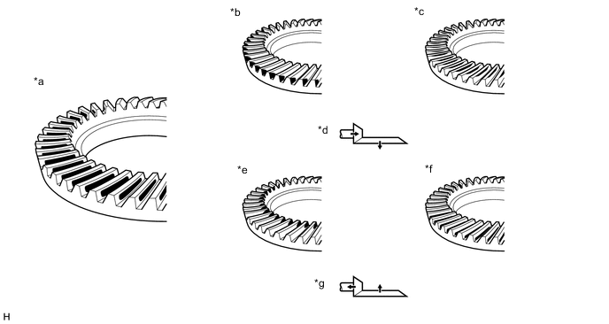
*a Proper Contact *b Heel Contact *c Face Contact *d Select an adjusting washer that will shift the drive pinion closer to the ring gear (*b, *c) *e Toe Contact *f Flank Contact *g Select an adjusting washer that will shift the drive pinion away from the ring gear (*e, *f) - - Inspect the tooth contact pattern.
Note:Check the tooth contact pattern at 4 or more positions around the circumference of the differential ring gear.
-
*1 Rear Differential Drive Pinion Plate Washer If the teeth are not contacting properly, use the following table to select a proper rear differential drive pinion plate washer for correction.
Tip:
-
If the contact pattern is face contact or flank contact, tooth contact may be adjustable while keeping the backlash within the specified range.
-
If the thickness of the rear differential drive pinion plate washer has been changed, adjust the backlash and measure the total preload.
Standard Plate Washer Part No. No. Thickness Part No. No. Thickness 90201-70002 88 1.87 to 1.89 mm (0.0736 to 0.0744 in.) 90201-70024 10 2.09 to 2.11 mm (0.0823 to 0.0830 in.) 90201-70004 90 1.89 to 1.91 mm (0.0745 to 0.0751 in.) 90201-70026 12 2.11 to 2.13 mm (0.0831 to 0.0838 in.) 90201-70006 92 1.91 to 1.93 mm (0.0752 to 0.0759 in.) 90201-70028 14 2.13 to 2.15 mm (0.0839 to 0.0846 in.) 90201-70008 94 1.93 to 1.95 mm (0.0760 to 0.0767 in.) 90201-70030 16 2.15 to 2.17 mm (0.0847 to 0.0854 in.) 90201-70010 96 1.95 to 1.97 mm (0.0768 to 0.0775 in.) 90201-70032 18 2.17 to 2.19 mm (0.0855 to 0.0862 in.) 90201-70012 98 1.97 to 1.99 mm (0.0776 to 0.0783 in.) 90201-70034 20 2.19 to 2.21 mm (0.0863 to 0.0870 in.) 90201-70014 00 1.99 to 2.01 mm (0.0784 to 0.0791 in.) 90201-70036 22 2.21 to 2.23 mm (0.0871 to 0.0877 in.) 90201-70016 02 2.01 to 2.03 mm (0.0792 to 0.0799 in.) 90201-70038 24 2.23 to 2.25 mm (0.0878 to 0.0885 in.) 90201-70018 04 2.03 to 2.05 mm (0.0780 to 0.0807 in.) 90201-70040 26 2.25 to 2.27 mm (0.0886 to 0.0893 in.) 90201-70020 06 2.05 to 2.07 mm (0.0808 to 0.0814 in.) 90201-70042 28 2.27 to 2.29 mm (0.0894 to 0.0901 in.) 90201-70022 08 2.07 to 2.09 mm (0.0815 to 0.0822 in.) - - - -
-
- Click here
REMOVE REAR DIFFERENTIAL SIDE GEAR SHAFT SHAFT SNAP RING (for RH Side)
- Click here
REMOVE REAR DIFFERENTIAL SIDE GEAR SHAFT SHAFT SNAP RING (for LH Side)
- Click here
REMOVE REAR DIFFERENTIAL CASE BEARING (for LH Side)
- Click here
REMOVE REAR DIFFERENTIAL CASE BEARING (for RH Side)
- Click here
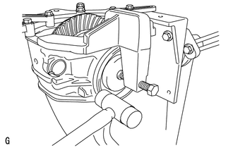
REMOVE REAR DIFFERENTIAL CASE SUB-ASSEMBLY
- Click here
REMOVE REAR DRIVE PINION NUT
-
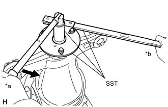
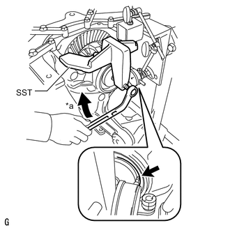
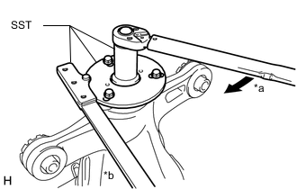
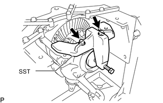
*a Turn *b Hold Using SST to hold the rear drive pinion companion flange, remove the rear drive pinion nut.
09229-55010 09330-00021 09950-30012 09955-03040 CAUTION:Hold the overhaul attachment during the operation.
Tip:When securing SST and the companion flange, it is recommended to use M8 X P 1.25 bolts with a length of approximately 45 mm.
-
- Click here
REMOVE REAR DRIVE PINION COMPANION FLANGE SUB-ASSEMBLY REAR
- Click here
REMOVE REAR DIFFERENTIAL DRIVE PINION OIL SLINGER
- Click here
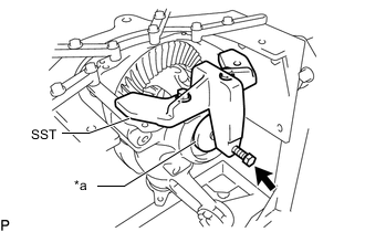
REMOVE DIFFERENTIAL DRIVE PINION
- Click here
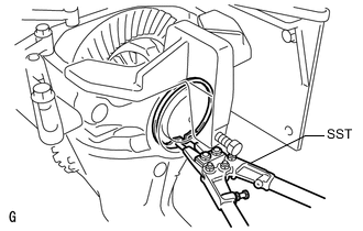
REMOVE REAR DRIVE PINION FRONT BEARING
-
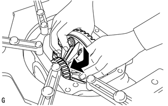
Remove the rear drive pinion front bearing (inner race) from the rear differential carrier.
-
- Click here
INSTALL REAR DIFFERENTIAL DRIVE PINION BEARING SPACER
-
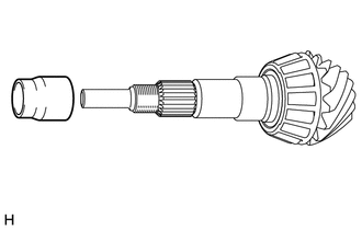
Install a new rear differential drive pinion bearing spacer to the differential drive pinion.
Note:Install the rear differential drive pinion bearing spacer with the larger diameter side facing toward the differential drive pinion.
-
- Click here
INSTALL DIFFERENTIAL DRIVE PINION
-
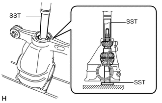
Using SST and a press, install the differential drive pinion to the rear differential carrier.
09316-60012 09316-00011 09316-00041 09608-04031
-
- Click here
INSTALL REAR DIFFERENTIAL DRIVE PINION OIL SLINGER
-
Install the rear differential drive pinion oil slinger.
-
- Click here
INSTALL REAR DIFFERENTIAL CARRIER OIL SEAL
- Click here
INSTALL REAR DRIVE PINION COMPANION FLANGE SUB-ASSEMBLY
-

*a Turn *b Hold Using SST, install the rear drive pinion companion flange to the differential drive pinion.
09950-30012 09951-03010 09953-03010 09954-03010 09955-03040 09956-03060 Note:Apply molybdenum grease to the threads of the SST center bolt (09953-03010) before use.
Tip:When securing SST and the companion flange, it is recommended to use M8 X P 1.25 bolts with a length of approximately 45 mm.
-
Coat the threads of a new rear drive pinion nut with hypoid gear oil LSD.
-
*a Turn *b Hold Using SST and a torque wrench, hold the rear drive pinion companion flange and temporary tighten the rear drive pinion nut.
09229-55010 09330-00021 09950-30012 09955-03040 490 N*m 4997 kgf*cm 361 ft.*lbf or less CAUTION:Hold the overhaul attachment during the operation.
Note:
-
Do not tighten the nut excessively, otherwise the threads will be stripped.
-
Apply hypoid gear oil LSD to the threads of the drive pinion nut and differential drive pinion.
Tip:Tighten the drive pinion nut to approximately 100 N*m (1020 kgf*cm, 74 ft.*lbf), and then tighten it further while observing the preload.
-
-
- Click here
INSTALL REAR DIFFERENTIAL CASE SUB-ASSEMBLY
-
Insert the rear differential case sub-assembly from the differential ring gear tooth side to install the rear differential case sub-assembly as shown in the illustration.
Note:Do not damage the rear differential case bearing and differential ring gear.
-
- Click here
INSTALL REAR DIFFERENTIAL CASE BEARING
-
Using SST and a hammer, install the rear differential case bearing (outer race) RH to the differential ring gear tooth side.
09608-32010 09950-70010 09951-07200 Tip:Tap in the rear differential case bearing (outer race) until half of the rear differential side gear shaft snap ring groove of the rear differential carrier can be seen.
-
*a Disc Install SST to the differential carrier with the 2 bolts (A) so that the center of the SST disc is at the center of the rear differential case bearing (outer race).
09571-10200 09571-01210 09571-01230 -
Tighten the SST bolt (B) until the SST disc lightly touches the rear differential case bearing (outer race) RH.
-
Using SST and a hammer, install the rear differential case bearing (outer race) LH to the differential ring gear back surface side.
09608-32010 09950-70010 09951-07200 Tip:Tap in the rear differential case bearing outer race until it touches the rear differential case bearing inner race roller.
-
- Click here
INSTALL REAR DIFFERENTIAL SIDE GEAR SHAFT SHAFT SNAP RING
-

Using SST, install the rear differential side gear shaft snap ring to the rear differential carrier on the differential ring gear back surface side.
09905-00031 Tip:Use the rear differential side gear shaft snap ring installed when performing tooth contact adjustment.
-

*a Turn Set a dial indicator on the rear differential carrier.
-
Tighten the SST bolt to alter the shape of the rear differential carrier by approximately 0.1 mm (0.00394 in.).
Note:Observe the dial indicator to ensure that the shape of the rear differential carrier does not change by more than 0.2 mm (0.00787 in.).
-

Using SST, install the rear differential side gear shaft snap ring to the differential ring gear tooth side.
09905-00031 Tip:Use the rear differential side gear shaft snap ring installed when performing tooth contact adjustment.
-
Remove the dial indicator and tap the rear differential carrier on the differential ring gear tooth side using a plastic-faced hammer to stabilize the rear differential case bearing.
-
Remove the 2 bolts and SST.
-
- Click here
ADJUST DIFFERENTIAL DRIVE PINION PRELOAD
-

Using SST and a torque wrench, measure the starting torque of the differential drive pinion.
09229-55010 Differential drive pinion preload (at starting) Item Specified Condition New bearing 1.25 to 1.65 N*m (12.8 to 16.8 kgf*cm, 11.1 to 14.6 in.*lbf) Reused bearing 1.25 to 1.65 N*m (12.8 to 16.8 kgf*cm, 11.1 to 14.6 in.*lbf)
-
If the preload is less than the specified minimum value, check the preload while retightening the rear drive pinion nut 5 to 10°.
Torque 490 N*m (4997 kgf*cm, 361 ft.*lbf) or less -
If the preload is less than the specified minimum value even when the tightening torque of the rear drive pinion nut is more than the specified maximum value, loosen the rear drive pinion nut and check that the threads of the drive pinion nut and differential drive pinion are not stripped.
-
If the threads are not stripped, replace the rear differential drive pinion bearing spacer. Apply hypoid gear oil LSD to the threads of the differential drive pinion and repeat the procedure.
Tip:
-
The backlash between the differential drive pinion and differential ring gear should allow enough movement of the differential drive pinion to allow this measurement to be performed.
-
Make sure not to include the preload of the differential ring gear (rear differential case sub-assembly) in the measurement of the differential drive pinion preload.
-
-
- Click here
INSPECT TOTAL PRELOAD
-
Using SST and a torque wrench, measure the preload with the teeth of the differential drive pinion and differential ring gear in contact.
09229-55010 Total Preload (at Starting) Item Specified Condition New bearing 1.75 to 3.04 N*m (17.9 to 30.9 kgf*cm, 15.5 to 26.9 in.*lbf) Reused bearing 1.62 to 2.63 N*m (16.6 to 26.8 kgf*cm, 14.4 to 23.2 in.*lbf)
-
- Click here
INSPECT DIFFERENTIAL RING GEAR BACKLASH
-
While holding the rear drive pinion companion flange, rotate the differential ring gear and measure the backlash.
Standard backlash 0.08 to 0.13 mm (0.00315 to 0.00512 in.) If the backlash is not within the specified range, adjust the backlash or perform repairs as necessary.
-
- Click here
INSPECT RUNOUT OF DIFFERENTIAL DRIVE PINION
-
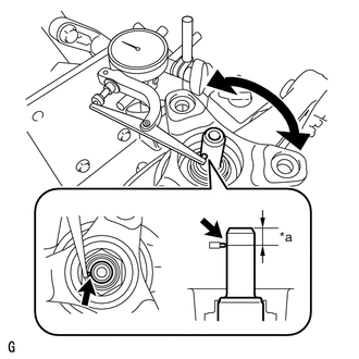
*a 10 mm (0.394 in.) Using a dial indicator, measure the runout of the differential drive pinion shaft at a position 10 mm (0.394 in.) away from the end of the shaft.
Maximum runout 0.08 mm (0.00315 in.) If the runout is more than the maximum, replace the differential drive pinion and differential ring gear.
-
- Click here
STAKE REAR DRIVE PINION NUT
-
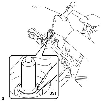
Using SST and a hammer, stake the rear drive pinion nut.
09930-00010
-
- Click here
INSTALL REAR DRIVE SHAFT OIL SEAL LH
-
*1 Rear Differential Side Gear Shaft Oil Seal *a Oil Seal Installation Depth Using SST and a hammer, install a new rear drive shaft oil seal LH.
09223-15030 09950-70010 09951-07150 Oil seal installation depth -0.5 to 0.5 mm (-0.0197 to 0.0196 in.) Note:
-
Make sure to check the identification marks on the rear differential side gear shaft oil seals before installation because the part numbers differ between the left and right sides.
-
To ensure a proper seal, evenly tap in the rear drive shaft oil seal LH.
-
When installing the rear drive shaft oil seal LH, tap them in until the outer surface of each seal is flush with the rear differential carrier.
-
Make sure the difference between the maximum and minimum measured values is less than 0.88 mm (0.0346 in.), as a greater difference may lead to oil leaks.
-
-
- Click here
INSTALL REAR DRIVE SHAFT OIL SEAL RH
Tip:Perform the same procedure as for the LH side.
- Click here
INSTALL REAR DIFFERENTIAL DRAIN PLUG
-
Using a 10 mm socket hexagon wrench, install the differential drain plug together with a new gasket.
49 N*m 500 kgf*cm 36 ft.*lbf
-
- Click here
REMOVE DIFFERENTIAL CARRIER ASSEMBLY REAR
-
Remove the 4 bolts and rear differential carrier from the overhaul stand.
Note:Clean the fitting surface between the rear differential carrier and rear differential carrier cover.
-
- Click here
INSTALL REAR DIFFERENTIAL BREATHER PLUG OIL DEFLECTOR
-
Clean the seal packing attached to the rear differential carrier and rear differential carrier cover using a scraper and wire brush. Then remove the oil with non-residue solvent or equivalent.
Note:Do not scratch the sealing surface.
-
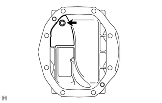
Install the rear differential breather plug oil deflector with the bolt while contacting it with the stoppers on the rear differential carrier cover.
7.0 N*m 71 kgf*cm 62 in.*lbf
-
- Click here
INSTALL REAR DIFFERENTIAL CARRIER STRAIGHT PIN
Tip:It is not necessary to remove a rear differential carrier straight pin unless it is being replaced.
-
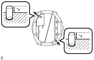
*a Protrusion Using a plastic-faced hammer, install the 2 rear differential carrier straight pins to the rear differential carrier cover.
Protrusion 10 to 12 mm (0.394 to 0.472 in.)
-
- Click here
INSTALL REAR DIFFERENTIAL CARRIER COVER
-

*a Seal Packing *b 2 to 3 mm (0.0788 to 0.1181 in.) Apply seal packing 1281 to the rear differential carrier as shown in the illustration.
Seal packing Toyota Genuine Seal Packing 1281, Three bond 1281 or equivalent Note:
-
Apply the seal packing in a continuous line, approximately 2 to 3 mm (0.0787 to 0.1181 in.) in diameter.
-
Overlap the seal packing at least 10 mm (0.394 in.) at the beginning and end of application.
-
Install the rear differential carrier cover within 3 minutes of application.
-
-
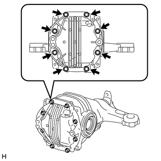
Install the rear differential carrier cover with the 8 bolts.
46.6 N*m 475 kgf*cm 34 ft.*lbf Note:Do not fill the differential with oil or drive the vehicle immediately after installing the differential carrier cover. Leave the vehicle for at least 1 hour. Also, avoid sudden acceleration and deceleration for at least 12 hours after application.
-
- Click here
INSTALL REAR DIFFERENTIAL BREATHER PLUG
-
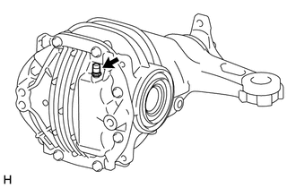
Install the rear differential breather plug to the rear differential carrier cover.
20.6 N*m 210 kgf*cm 15 ft.*lbf
-
- Click here
INSTALL REAR DIFFERENTIAL DYNAMIC DAMPER
-
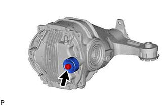
Using a 12 mm socket hexagon wrench, install the rear differential dynamic damper to the rear differential carrier cover with the bolt.
103 N*m 1050 kgf*cm 76 ft.*lbf
-