PROCEDURE
- Click here
INSTALL DIFFERENTIAL RING GEAR
-
Clean the differential ring gear set bolt hole.
-
Heat the differential ring gear to approximately 100°C (212°F) in boiling water.
CAUTION:Use thick gloves to protect your hands as the differential ring gear is hot.
-
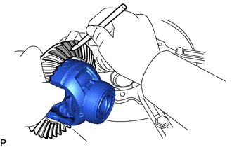
Carefully take the differential ring gear out of the boiling water.
-
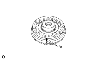
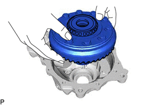
*a Matchmark After the moisture on the differential ring gear has completely evaporated, quickly install the differential ring gear to the No. 1 front differential case sub-assembly.
Tip:Align the matchmarks, differential case bolt holes and differential ring gear screw holes.
-
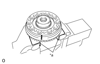
*a Aluminum Plate Hold the No. 1 front differential case sub-assembly in a vise between aluminum plates.
Note:Do not overtighten the vise.
-
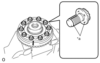
*a Adhesive Apply adhesive to the threads and flanges of 10 new differential ring gear set bolts.
96.5 N*m 984 kgf*cm 71 ft.*lbf Adhesive Toyota Genuine Adhesive 1360K, Three Bond 1360K or equivalent Note:
-
Tighten the bolts after the differential ring gear has sufficiently cooled down.
-
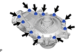
Install the differential case bolts by tightening diametrically opposite pairs uniformly in several passes.
-
-
- Click here
INSTALL FRONT DRIVE PINION REAR TAPERED ROLLER BEARING
-
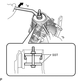
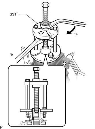
*a Turn *b Hold Using SST, a bolt, nut, and washer, install the front drive pinion front tapered roller bearing outer race to the differential carrier.
09950-60021 09951-00730 09951-00810 Note:
-
New bearings are coated with anti-rust oil. If using new bearings, do not clean off this coating.
-
Do not apply hypoid gear oil to a new bearing.
-
If reusing a bearing, coat it with Toyota Genuine Differential gear oil LT SAE 75W-85 API GL-5 or equivalent.
-
If the bearing is replaced, replace the bearing (inner race) and bearing (outer race) as a set.
Tip:Use bolts with a size of M12 x P1.25 with a bolt length beneath the head of 145 mm (5.71 in.).
-
-
- Click here
INSTALL FRONT DRIVE PINION FRONT TAPERED ROLLER BEARING
-
Install the front drive pinion spacer adjust shim to the differential carrier.
Tip:Select a front drive pinion spacer adjust shim of the same thickness as the one removed.
-
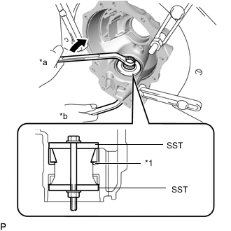
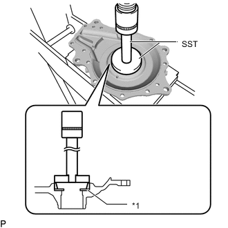
*1 Front Drive Pinion Spacer Adjust Shim *a Turn *b Hold Using SST, a bolt, nut, and washer, install the front drive pinion front tapered roller bearing outer race to the differential carrier.
09950-60021 09951-00730 09951-00810 Note:
-
New bearings are coated with anti-rust oil. If using new bearings, do not clean off this coating.
-
Do not apply hypoid gear oil to a new bearing.
-
If reusing a bearing, coat it with Toyota Genuine Differential gear oil LT SAE 75W-85 API GL-5 or equivalent.
-
If the bearing is replaced, replace the bearing (inner race) and bearing (outer race) as a set.
Tip:Use bolts with a size of M12 x P1.25 with a bolt length beneath the head of 145 mm (5.71 in.).
-
-
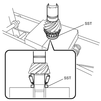
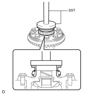
Using SST and a press, press in the front drive pinion front tapered roller bearing inner race to the drive pinion.
09309-14020 Note:
-
New bearings are coated with anti-rust oil. If using new bearings, do not clean off this coating.
-
Do not apply hypoid gear oil to a new bearing.
-
If reusing a bearing, coat it with Toyota Genuine Differential gear oil LT SAE 75W-85 API GL-5 or equivalent.
-
If the bearing is replaced, replace the bearing (inner race) and bearing (outer race) as a set.
-
-
- Click here
INSTALL FRONT DIFFERENTIAL CASE BEARING LH
-
Remove the differential carrier from the overhaul attachment.
-
Install the differential case washer to the differential carrier.
Tip:
-
If the final gear set (drive pinion and ring gear) or front differential case bearing LH are replaced, select and install the thinnest differential case washer first.
-
If the drive pinion, ring gear or differential case are reused, select and install a differential case washer with the same thickness as the one before the disassembly first.
-
-
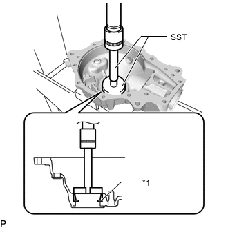
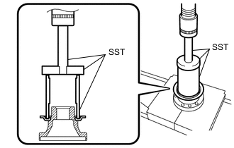
*1 Differential Case Washer Using SST and a press, press in the front differential case bearing LH (outer race) to the differential carrier.
09950-60021 09951-00790 09950-70010 09951-07200 Note:
-
New bearings are coated with anti-rust oil. If using new bearings, do not clean off this coating.
-
Do not apply hypoid gear oil to a new bearing.
-
If reusing a bearing, coat it with Toyota Genuine Differential gear oil LT SAE 75W-85 API GL-5 or equivalent.
-
If the bearing is replaced, replace the bearing (inner race) and bearing (outer race) as a set.
-
-
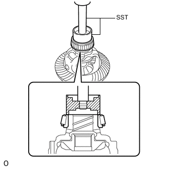
Using SST and a press, press the front differential case bearing LH (inner race) onto the No. 1 front differential case sub-assembly.
09710-30050 09950-70010 09951-07100 Note:
-
New bearings are coated with anti-rust oil. If using new bearings, do not clean off this coating.
-
Do not apply hypoid gear oil to a new bearing.
-
If reusing a bearing, coat it with Toyota Genuine Differential gear oil LT SAE 75W-85 API GL-5 or equivalent.
-
If the bearing is replaced, replace the bearing (inner race) and bearing (outer race) as a set.
-
Be careful not to deform the front differential case bearing LH.
-
-
- Click here
INSTALL FRONT DIFFERENTIAL CASE BEARING RH
-
Using SST and a press, press a new front differential case bearing RH (inner race) onto the No. 1 front differential case sub-assembly.
09316-12010 09950-70010 09951-07100 09951-00900 Note:
-
New bearings are coated with anti-rust oil. If using new bearings, do not clean off this coating.
-
Do not apply hypoid gear oil to a new bearing.
-
If reusing a bearing, coat it with Toyota Genuine Differential gear oil LT SAE 75W-85 API GL-5 or equivalent.
-
If the bearing is replaced, replace the bearing (inner race) and bearing (outer race) as a set.
-
-
Install the differential case washer to the front differential carrier retainer sub-assembly.
Tip:
-
If the final gear set (drive pinion and ring gear) or front differential case bearing RH are replaced, select and install the thinnest differential case washer first.
-
If the drive pinion, ring gear or differential case are reused, select and install a differential case washer with the same thickness as the one before the disassembly first.
-
-
*1 Differential Case Washer Using SST and a press, press in the front differential case bearing RH (outer race) to the front differential carrier retainer sub-assembly.
Note:
-
New bearings are coated with anti-rust oil. If using new bearings, do not clean off this coating.
-
Do not apply hypoid gear oil to a new bearing.
-
If reusing a bearing, coat it with Toyota Genuine Differential gear oil LT SAE 75W-85 API GL-5 or equivalent.
-
If the bearing is replaced, replace the bearing (inner race) and bearing (outer race) as a set.
09950-60021 09951-00890 09950-70010 09951-07100 -
-
- Click here
INSTALL FRONT DIFFERENTIAL DUST DEFLECTOR
-
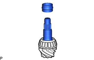
Using SST and a press, insert a new front differential dust deflector into the front drive pinion companion flange front sub-assembly.
09612-30012 09950-70010 09951-07100 Note:
-
Slowly press in the front differential dust deflector but not excessively.
-
If any burrs remain after pressing in the deflector, remove them.
-
-
- Click here
ADJUST DRIVE PINION PRELOAD
-
Fix the differential carrier with an attachment.
-
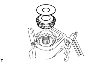
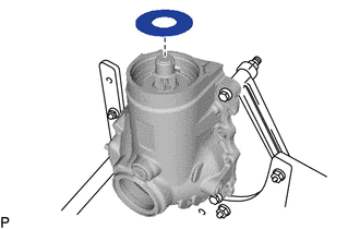
Install the differential drive pinion to the differential carrier, and then install the front drive pinion rear tapered roller bearing inner race and front differential drive pinion oil slinger while supporting the differential drive pinion by hand.
Note:
-
New bearings are coated with anti-rust oil. If using new bearings, do not clean off this coating.
-
Do not apply hypoid gear oil to a new bearing.
-
If reusing a bearing, coat it with Toyota Genuine Differential gear oil LT SAE 75W-85 API GL-5 or equivalent.
-
Do not drop the differential drive pinion.
Tip:Install the front differential drive pinion bearing spacer and front differential carrier oil seal after performing the ring gear tooth contact pattern inspection adjustment.
-
-
*a Turn *b Hold Using SST, install the front drive pinion companion flange front sub-assembly.
09950-30012 09951-03010 09953-03010 09954-03010 09955-03030 09956-03020 Note:
-
As a front differential drive pinion bearing spacer is not installed, if SST is tightened excessively, SST, the front drive pinion companion flange front sub-assembly, and differential drive pinion will be damaged.
-
Support the differential drive pinion by hand until SST is installed.
-
Be careful not to drop the differential drive pinion.
Tip:
-
Before using SST center bolt, apply hypoid gear oil to its threads and tip.
-
Install the front drive pinion companion flange front sub-assembly so that there is some free play in the drive pinion.
-
-
Remove SST.
-
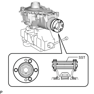
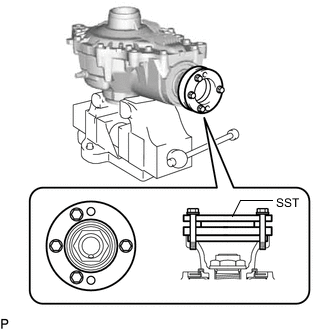
Install SST to the flange as shown in the illustration.
25 N*m 255 kgf*cm 18 ft.*lbf 09213-58014 Note:
-
Use the 4 bolts with part number 90119-08B87.
-
Use bolts with a size of M6 x P1.25 with a bolt length beneath the head of 55 mm.
-
-
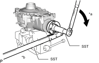
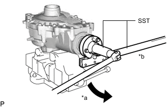
*a Turn *b Hold Using SST and a torque wrench, tighten the flange nut little by little until it reaches the specified preload.
09229-55010 09330-00021 Maximum torque 490 N*m (4996 kgf*cm, 361 ft.*lbf) Note:
-
Tighten the nut with a force of 100 N*m (1020 kgf*cm. 74 in.*lbf) while checking the starting torque of the differential drive pinion.
-
As the front differential drive pinion bearing spacer is not installed, tighten the flange nut little by little. Do not overtighten the nut.
-
Do not overtighten the nut, as the threads will become damaged.
-
Coat the threads the flange nut and differential drive pinion with hypoid gear oil LSD.
-
Perform the installment while supporting the overhaul attachment.
-
-
Using SST and a torque wrench, measure the preload.
09229-55010 Standard drive pinion preload (at starting) New bearing 4.26 to 4.95 N*m (43.5 to 50.4 kgf*cm, 37.8 to 43.8 in.*lbf) Reused bearing 3.06 to 3.53 N*m (31.3 to 35.9 kgf*cm, 27.1 to 31.2 in.*lbf) Note:For a more accurate measurement, rotate the bearing forward and backward before the inspection.
Tip:Record the preload for total preload measurement.
-
- Click here
INSTALL NO. 1 FRONT DIFFERENTIAL CASE SUB-ASSEMBLY WITH RING GEAR
-
Remove the differential carrier from the overhaul attachment.
-
Install the No. 1 front differential case sub-assembly with ring gear to the differential carrier.
Note:Do not damage the 2 front differential case bearings and differential ring gear.
-
- Click here
INSPECT AND ADJUST DIFFERENTIAL RING GEAR BACKLASH
-
Install the front differential carrier retainer sub-assembly to the differential carrier with the 11 bolts.
58 N*m 591 kgf*cm 43 ft.*lbf -
Install the differential carrier to the overhaul attachment.
-
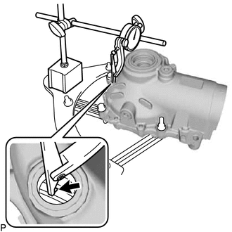
Connect a lever probe to a dial indicator. Insert the probe into the drain plug hole and set it onto the edge of one of the teeth of the ring gear at a right angle.
-
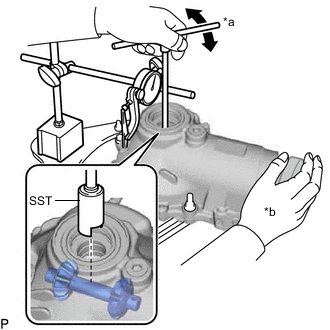
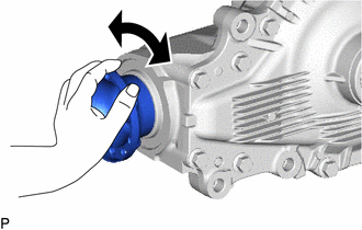
*a Turn *b Hold Using SST, turn the differential case clockwise and counterclockwise and measure the ring gear backlash while holding the companion flange with your hand.
09564-50010 Standard backlash 0.15 to 0.23 mm (0.00591 to 0.00905 in.) Tip:
-
Measure at 3 or more areas around the circumference of the differential ring gear.
-
Record the measured value, as it is used to select the differential case washer.
-
If the result is outside of the standard range, replace the differential case washer with one of a different thickness in accordance with the following procedure.
-
Perform the tooth contact pattern inspection for the differential ring gear and differential drive pinion. The results will be used as a reference for selecting the differential case washer LH and RH.
-
-
Select a differential case washer from the table until the backlash measured value is in the standard range.
Differential case washer thickness (LH) Parts No Thickness Parts No Thickness 90564-51140 2.11 to 2.13 mm (0.0831 to 0.0839 in.) 90564-51112 2.59 to 2.61 mm (0.1020 to 0.1027 in.) 90564-51141 2.13 to 2.15 mm (0.0839 to 0.0846 in.) 90564-51113 2.61 to 2.63 mm (0.1028 to 0.1035 in.) 90564-51090 2.15 to 2.17 mm (0.0846 to 0.0854 in.) 90564-51114 2.63 to 2.65 mm (0.1036 to 0.1043 in.) 90564-51091 2.17 to 2.19 mm (0.0854 to 0.0862 in.) 90564-51115 2.65 to 2.67 mm (0.1044 to 0.1051 in.) 90564-51092 2.19 to 2.21 mm (0.0863 to 0.0870 in.) 90564-51116 2.67 to 2.69 mm (0.1052 to 0.1059 in.) 90564-51093 2.21 to 2.23 mm (0.0871 to 0.0877 in.) 90564-51117 2.69 to 2.71 mm (0.1060 to 0.1066 in.) 90564-51094 2.23 to 2.25 mm (0.0878 to 0.0885 in.) 90564-51118 2.71 to 2.73 mm (0.1067 to 0.1074 in.) 90564-51095 2.25 to 2.27 mm (0.0886 to 0.0893 in.) 90564-51119 2.73 to 2.75 mm (0.1075 to 0.1082 in.) 90564-51096 2.27 to 2.29 mm (0.0894 to 0.0901 in.) 90564-51120 2.75 to 2.77 mm (0.1083 to 0.1090 in.) 90564-51097 2.29 to 2.31 mm (0.0902 to 0.0909 in.) 90564-51121 2.77 to 2.79 mm (0.1091 to 0.1098 in.) 90564-51098 2.31 to 2.33 mm (0.0910 to 0.0917 in.) 90564-51122 2.79 to 2.81 mm (0.1099 to 0.1106 in.) 90564-51099 2.33 to 2.35 mm (0.0918 to 0.0925 in.) 90564-51123 2.81 to 2.83 mm (0.1107 to 0.1114 in.) 90564-51100 2.35 to 2.37 mm (0.0926 to 0.0933 in.) 90564-51124 2.83 to 2.85 mm (0.1115 to 0.1122 in.) 90564-51101 2.37 to 2.39 mm (0.0934 to 0.0940 in.) 90564-51125 2.85 to 2.87 mm (0.1123 to 0.1129 in.) 90564-51102 2.39 to 2.41 mm (0.0941 to 0.0948 in.) 90564-51126 2.87 to 2.89 mm (0.1130 to 0.1137 in.) 90564-51103 2.41 to 2.43 mm (0.0949 to 0.0956 in.) 90564-51127 2.89 to 2.91 mm (0.1138 to 0.1145 in.) 90564-51104 2.43 to 2.45 mm (0.0957 to 0.0964 in.) 90564-51128 2.91 to 2.93 mm (0.1146 to 0.1153 in.) 90564-51105 2.45 to 2.47 mm (0.0965 to 0.0972 in.) 90564-51129 2.93 to 2.95 mm (0.1154 to 0.1161 in.) 90564-51106 2.47 to 2.49 mm (0.0973 to 0.0980 in.) 90564-51130 2.95 to 2.97 mm (0.1162 to 0.1169 in.) 90564-51107 2.49 to 2.51 mm (0.0981 to 0.0988 in.) 90564-51131 2.97 to 2.99 mm (0.1170 to 0.1177 in.) 90564-51108 2.51 to 2.53 mm (0.0989 to 0.0996 in.) 90564-51132 2.99 to 3.01 mm (0.1178 to 0.1185 in.) 90564-51109 2.53 to 2.55 mm (0.0997 to 0.1003 in.) 90564-51133 3.01 to 3.03 mm (0.1186 to 0.1192 in.) 90564-51110 2.55 to 2.57 mm (0.1004 to 0.1011 in.) 90564-51134 3.03 to 3.05 mm (0.1193 to 0.1201 in.) 90564-51111 2.57 to 2.59 mm (0.1012 to 0.1019 in.) - - Differential case washer thickness (RH) Parts No Thickness Parts No Thickness 90564-39049 2.09 to 2.11 mm (0.0823 to 0.0830 in.) 90564-39021 2.59 to 2.61 mm (0.1020 to 0.1027 in.) 90564-39050 2.11 to 2.13 mm (0.0831 to 0.0838 in.) 90564-39022 2.61 to 2.63 mm (0.1028 to 0.1035 in.) 90564-39051 2.13 to 2.15 mm (0.0839 to 0.0846 in.) 90564-39023 2.63 to 2.65 mm (0.1036 to 0.1043 in.) 90564-39052 2.15 to 2.17 mm (0.0847 to 0.0854 in.) 90564-39024 2.65 to 2.67 mm (0.1044 to 0.1051 in.) 90564-39053 2.17 to 2.19 mm (0.0855 to 0.0862 in.) 90564-39025 2.67 to 2.69 mm (0.1052 to 0.1059 in.) 90564-39001 2.19 to 2.21 mm (0.0863 to 0.0870 in.) 90564-39026 2.69 to 2.71 mm (0.1060 to 0.1066 in.) 90564-39002 2.21 to 2.23 mm (0.0871 to 0.0877 in.) 90564-39027 2.71 to 2.73 mm (0.1067 to 0.1074 in.) 90564-39003 2.23 to 2.25 mm (0.0878 to 0.0885 in.) 90564-39028 2.73 to 2.75 mm (0.1075 to 0.1082 in.) 90564-39004 2.25 to 2.27 mm (0.0886 to 0.0893 in.) 90564-39029 2.75 to 2.77 mm (0.1083 to 0.1090 in.) 90564-39005 2.27 to 2.29 mm (0.0894 to 0.0901 in.) 90564-39030 2.77 to 2.79 mm (0.1091 to 0.1098 in.) 90564-39006 2.29 to 2.31 mm (0.0902 to 0.0909 in.) 90564-39031 2.79 to 2.81 mm (0.1099 to 0.1106 in.) 90564-39007 2.31 to 2.33 mm (0.0910 to 0.0917 in.) 90564-39032 2.81 to 2.83 mm (0.1107 to 0.1114 in.) 90564-39008 2.33 to 2.35 mm (0.0918 to 0.0925 in.) 90564-39033 2.83 to 2.85 mm (0.1115 to 0.1122 in.) 90564-39009 2.35 to 2.37 mm (0.0926 to 0.0933 in.) 90564-39034 2.85 to 2.87 mm (0.1123 to 0.1129 in.) 90564-39010 2.37 to 2.39 mm (0.0934 to 0.0940 in.) 90564-39035 2.87 to 2.89 mm (0.1130 to 0.1137 in.) 90564-39011 2.39 to 2.41 mm (0.0941 to 0.0948 in.) 90564-39036 2.89 to 2.91 mm (0.1138 to 0.1145 in.) 90564-39012 2.41 to 2.43 mm (0.0949 to 0.0956 in.) 90564-39037 2.91 to 2.93 mm (0.1146 to 0.1153 in.) 90564-39013 2.43 to 2.45 mm (0.0957 to 0.0964 in.) 90564-39038 2.93 to 2.95 mm (0.1154 to 0.1161 in.) 90564-39014 2.45 to 2.47 mm (0.0965 to 0.0972 in.) 90564-39039 2.95 to 2.97 mm (0.1162 to 0.1169 in.) 90564-39015 2.47 to 2.49 mm (0.0973 to 0.0980 in.) 90564-39040 2.97 to 2.99 mm (0.1170 to 0.1177 in.) 90564-39016 2.49 to 2.51 mm (0.0981 to 0.0988 in.) 90564-39041 2.99 to 3.01 mm (0.1178 to 0.1185 in.) 90564-39017 2.51 to 2.53 mm (0.0989 to 0.0996 in.) 90564-39042 3.01 to 3.03 mm (0.1186 to 0.1192 in.) 90564-39018 2.53 to 2.55 mm (0.0997 to 0.1003 in.) 90564-39043 3.03 to 3.05 mm (0.1193 to 0.1200 in.) 90564-39019 2.55 to 2.57 mm (0.1004 to 0.1011 in.) 90564-39044 3.05 to 3.07 mm (0.1201 to 0.1208 in.) 90564-39020 2.57 to 2.59 mm (0.1012 to 0.1019 in.) - - Tip:
-
Make sure to increase the thickness of the LH and RH differential case washer by the same amount each time until the backlash is in the standard range.
-
Perform the tooth contact pattern inspection for the differential ring gear and differential drive pinion. The results will be used as a reference for selecting the differential case washer LH and RH.
-
When adjusting the backlash, adjust to within 0.18 mm (0.00709 in.) of the average of the measurements.
-
-
- Click here
INSPECT AND ADJUST TOTAL PRELOAD
-
Using SST and a torque wrench, measure the preload with the teeth of the differential drive pinion and differential ring gear in contact.
09229-55010 Standard total preload New bearing 4.92 to 5.85 N*m (50.2 to 59.6 kgf*cm, 43.6 to 51.7 in.*lbf) Reused bearing 3.51 to 4.18 N*m (35.8 to 42.6 kgf*cm, 31.1 to 36.9 in.*lbf) Tip:
-
When the value is outside the standard range, adjust using the differential case washer on the differential ring gear tooth side.
-
When the value is less than the lower limit of the standard range, replace the differential case washer with a thicker one.
-
When the value is more than the upper limit of the standard range, replace the differential case washer with a thinner one.
-
For reassembly purposes, record the measured value.
-
-
Connect a lever probe to a dial indicator. Insert the probe into the drain plug hole and set it onto the edge of one of the teeth of the differential ring gear at a right angle.
-
*a Turn *b Hold Using SST, turn the differential case clockwise and counterclockwise and measure the differential ring gear backlash while holding the front drive pinion companion flange front sub-assembly with your hand.
09564-50010 Standard backlash 0.15 to 0.23 mm (0.00591 to 0.00905 in.) Tip:
-
Measure at 3 or more areas around the circumference of the differential ring gear.
-
If the backlash is not in the standard range, increase the LH and RH differential case washer by the same amount until the backlash is in the standard range.
-
Record the measured value and use it when selecting the differential case washer.
-
Perform the tooth contact pattern inspection for the differential ring gear and differential drive pinion. The results will be used as a reference for selecting the differential case washer LH and RH.
-
When adjusting the backlash, adjust to within 0.18 mm (0.00709 in.) of the average of the measurements.
-
-
Recheck the total preload.
-
- Click here
INSPECT TOOTH CONTACT BETWEEN RING GEAR AND DRIVE PINION
-
Remove the differential carrier from the overhaul attachment.
-
Remove the 11 bolts and front differential carrier retainer sub-assembly from the differential carrier.
-
Remove the No. 1 front differential case sub-assembly with ring gear from the differential carrier.
Note:Do not damage the front differential case bearings and differential ring gear.
-
Uniformly apply a light coat of Prussian blue on both sides of 4 teeth on the differential ring gear.
-
Install the No. 1 front differential case sub-assembly with ring gear to the differential carrier.
Note:Do not damage the front differential case bearings and differential ring gear.
-
Install the front differential carrier retainer sub-assembly to the differential carrier with the 11 bolts.
58 N*m 591 kgf*cm 43 ft.*lbf -
Rotate the companion flange several times in the forward and backward rotation directions.
-
Remove the 11 bolts and front differential carrier retainer sub-assembly from the differential carrier.
-
Remove the No. 1 front differential case sub-assembly with ring gear from the differential carrier.
Note:Do not damage the front differential case bearing and differential ring gear.
-
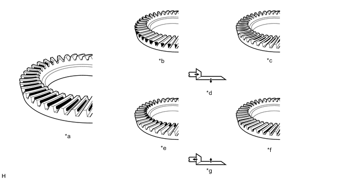
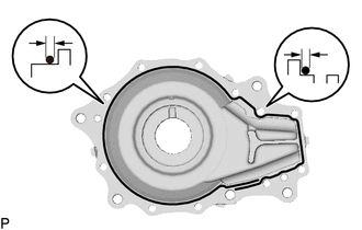
*a Proper Contact *b Heel Contact *c Face Contact *d Select an adjusting washer that will shift the drive pinion closer to the ring gear (*b, *c) *e Toe Contact *f Flank Contact *g Select an adjusting washer that will shift the drive pinion away from to the ring gear (*e, *f) - - Inspect the tooth contact pattern.
Note:Check the tooth contact pattern at 4 or more positions around the circumference of the differential ring gear.
Tip:The patterns indicated by the Prussian blue are the tooth contact locations.
-

*1 Front Drive Pinion Spacer Adjust Shim If the tooth contact is not proper, select a front drive pinion spacer adjust shim from the table and perform the tooth contact pattern inspection again.
Note:
-
It is possible for the backlash to be adjusted within the standard range in instances of face contact and flank contact.
-
If the thickness of the front drive pinion spacer adjust shim changes, perform the backlash adjustment and inspect the total preload.
Front Drive Pinion Spacer Adjust Shim Thickness Parts No Thickness Parts No Thickness 90564-62051 0.99 to 1.01 mm (0.0390 to 0.0397 in.) 90564-62064 1.25 to 1.27 mm (0.0493 to 0.0499 in.) 90564-62052 1.01 to 1.03 mm (0.0398 to 0.0405 in.) 90564-62065 1.27 to 1.29 mm (0.0500 to 0.0507 in.) 90564-62053 1.03 to 1.05 mm (0.0406 to 0.0413 in.) 90564-62066 1.29 to 1.31 mm (0.0508 to 0.0515 in.) 90564-62054 1.05 to 1.07 mm (0.0414 to 0.0421 in.) 90564-62067 1.31 to 1.33 mm (0.0516 to 0.0523 in.) 90564-62055 1.07 to 1.09 mm (0.0422 to 0.0429 in.) 90564-62068 1.33 to 1.35 mm (0.0524 to 0.0531 in.) 90564-62056 1.09 to 1.11 mm (0.0430 to 0.0437 in.) 90564-62069 1.35 to 1.37 mm (0.0532 to 0.0539 in.) 90564-62057 1.11 to 1.13 mm (0.0438 to 0.0444 in.) 90564-62070 1.37 to 1.39 mm (0.0540 to 0.0547 in.) 90564-62058 1.13 to 1.15 mm (0.0445 to 0.0452 in.) 90564-62071 1.39 to 1.41 mm (0.0548 to 0.0555 in.) 90564-62059 1.15 to 1.17 mm (0.0453 to 0.0460 in.) 90564-62072 1.41 to 1.43 mm (0.0556 to 0.0562 in.) 90564-62060 1.17 to 1.19 mm (0.0461 to 0.0468 in.) 90564-62073 1.43 to 1.45 mm (0.0563 to 0.0570 in.) 90564-62061 1.19 to 1.21 mm (0.0469 to 0.0476 in.) 90564-62074 1.45 to 1.47 mm (0.0571 to 0.0578 in.) 90564-62062 1.21 to 1.23 mm (0.0477 to 0.0484 in.) 90564-62075 1.47 to 1.49 mm (0.0579 to 0.0586 in.) 90564-62063 1.23 to 1.25 mm (0.0485 to 0.0492 in.) - - -
-
- Click here
REMOVE DIFFERENTIAL CASE
- Click here
REMOVE FRONT DRIVE PINION COMPANION FLANGE FRONT NUT
-
Install SST to the flange as shown in the illustration.
09213-58014 Note:
-
Use the 4 bolts with part number 90119-08B87.
-
Use bolts with a size of M6 x P1.25 with a bolt length beneath the head of 55 mm.
-
-
*a Turn *b Hold Using SST to hold the flange, remove the front drive pinion companion flange front nut.
09330-00021 09229-55010 Note:Perform the removal while supporting the overhaul attachment.
-
- Click here
REMOVE FRONT DRIVE PINION COMPANION FLANGE FRONT SUB-ASSEMBLY
- Click here
REMOVE FRONT DIFFERENTIAL DRIVE PINION OIL SLINGER
- Click here
REMOVE DIFFERENTIAL DRIVE PINION
- Click here
INSTALL FRONT DIFFERENTIAL DRIVE PINION BEARING SPACER
-
Install a new front differential drive pinion bearing spacer to the differential drive pinion.
-
- Click here
INSTALL FRONT DRIVE PINION REAR TAPERED ROLLER BEARING INNER RACE
-
*a Turn *b Hold Using SST and the front drive pinion companion flange front sub-assembly, press the front drive pinion rear tapered roller bearing inner race into the differential carrier.
09950-30012 09951-03010 09953-03010 09954-03010 09955-03040 09956-03060 Note:
-
As the differential drive pinion is supported by hand until SST is installed, be careful not to drop the differential drive pinion.
-
Apply grease to the threads and tip of SST center bolt before use.
-
-
Using SST, remove the front drive pinion companion flange front sub-assembly from the differential carrier.
Tip:Before using SST center bolt, apply hypoid gear oil to its threads and tip.
-
- Click here
INSTALL FRONT DIFFERENTIAL DRIVE PINION OIL SLINGER
-
Install the front differential drive pinion oil slinger to the differential carrier.
-
- Click here
INSTALL FRONT DIFFERENTIAL CARRIER OIL SEAL
- Click here
INSTALL FRONT DIFFERENTIAL BREATHER PLUG OIL DEFLECTOR
-
Install the front differential breather plug oil deflector to the differential carrier with the 2 bolts.
7.0 N*m 71 kgf*cm 62 in.*lbf
-
- Click here
INSTALL FRONT DRIVE PINION COMPANION FLANGE FRONT SUB-ASSEMBLY
-
*a Turn *b Hold Using SST, install the front drive pinion companion flange front sub-assembly to the drive pinion.
09950-30012 09951-03010 09953-03010 09954-03010 09955-03040 09956-03060 Note:Do not insert the front drive pinion companion flange front sub-assembly excessively as the preload will be adjusted in the following procedure.
Tip:Before using SST center bolt, apply hypoid gear oil to its threads and tip.
-
- Click here
INSPECT DRIVE PINION PRELOAD
-
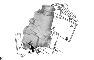
Install SST to the flange as shown in the illustration.
25 N*m 255 kgf*cm 18 ft.*lbf 09213-58014 Note:
-
Use the 4 bolts with part number 90119-08B87.
-
Use bolts with a size of M6 x P1.25 with a bolt length beneath the head of 55 mm.
-
-
Coat the threads of a new front drive pinion companion flange front nut with hypoid gear oil LSD.
-
*a Turn *b Hold Using SST to hold the flange, install the front drive pinion companion flange front nut.
09330-00021 09229-55010 Maximum torque 490 N*m (4996 kgf*cm, 361 ft.*lbf) Note:
-
Tighten the flange nut little by little to reach the specified preload, being careful not to exceed the maximum torque.
-
Do not overtighten the nut, as the threads will become damaged.
-
Measure the preload after rotating the front drive pinion companion flange front sub-assembly several times in the forward and backward directions to make sure the bearing is operating correctly.
-
Perform the installation while supporting the overhaul attachment.
-
-
Using SST and a torque wrench, measure the drive pinion preload.
09229-55010 Tip:Record the drive pinion preload for the total preload inspection.
Standard drive pinion preload (at starting) New bearing 4.47 to 5.16 N*m (45.6 to 52.6 kgf*cm, 39.6 to 45.6 in.*lbf) Reused bearing 3.3 to 3.7 N*m (33.7 to 37.7 kgf*cm, 29.3 to 32.7 in.*lbf) Note:The front differential drive pinion bearing spacer is made of plastic and changes shape when used. If the starting torque of the differential drive pinion is exceeded by mistake, make sure to replace the front differential drive pinion bearing spacer with a new one.
Tip:
-
If the preload is insufficient, tighten the nut 5 to 10° at a time until the preload is in the standard range.
-
If the tightening torque of the flange nut exceeds the specified torque but the preload is still insufficient, loosen the flange nut. Then check if the flange nut and drive pinion threads are damaged.
-
If there are no problems, replace the front differential drive pinion bearing spacer, apply hypoid gear oil LSD to the threads of the front drive pinion companion flange front nut and repeat the procedure above.
-
-
- Click here
INSTALL NO. 1 FRONT DIFFERENTIAL CASE SUB-ASSEMBLY
-
Remove the differential carrier from the overhaul attachment.
-
Install the No. 1 front differential case sub-assembly to the differential carrier.
Note:Do not damage the front differential case bearing and differential ring gear.
-
- Click here
INSTALL FRONT DIFFERENTIAL CARRIER RETAINER SUB-ASSEMBLY
-
Remove the seal packing attached on the differential carrier and front differential carrier retainer sub-assembly using a scraper and wire brush.
Note:Do not scratch the fitting surface.
-
Check that there is no foreign matter or damage on the installation surface of the front differential carrier retainer sub-assembly.
-
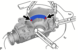
Apply seal packing to the front differential carrier retainer sub-assembly as shown in the illustration.
Seal packing Toyota Genuine Seal Packing 1281, Three bond 1281 or equivalent Note:
-
Apply the seal packing in a continuous line, approximately 2 to 3 mm (0.0788 to 0.118 in.) in diameter.
-
Overlap the seal packing at least 10 mm (0.394 in.) at the beginning and the end of application.
-
Install the front differential carrier retainer sub-assembly within 3 minutes of application.
-
-
Install the front differential carrier retainer sub-assembly with the 11 bolts.
58 N*m 591 kgf*cm 43 ft.*lbf Note:Do not fill the oil or drive immediately after installing the front differential carrier retainer sub-assembly. Leave the vehicle for at least 1 hour. Also, avoid sudden acceleration and deceleration for at least 12 hours after application.
-

Set the differential carrier to an overhaul stand as shown in the illustration.
-
- Click here
INSTALL FRONT DIFFERENTIAL BREATHER PLUG
-
Install the front differential breather plug to the differential carrier.
21 N*m 214 kgf*cm 15 ft.*lbf
-
- Click here
INSPECT TOTAL PRELOAD
-
Using SST and a torque wrench, measure the preload with the teeth of the differential drive pinion and differential ring gear in contact.
09229-55010 Standard total preload New bearing 5.13 to 6.06 N*m (52.4 to 61.7 kgf*cm, 45.5 to 53.6 in.*lbf) Reused bearing 3.72 to 4.39 N*m (38.0 to 44.7 kgf*cm, 33.0 to 38.8 in.*lbf)
-
- Click here
INSPECT DIFFERENTIAL RING GEAR BACKLASH
-
Connect a lever probe to a dial indicator. Insert the probe into the drain plug hole and set it onto the edge of one of the teeth of the differential ring gear at a right angle.
-
*a Turn *b Hold Using SST, turn the differential case clockwise and counterclockwise and measure the differential ring gear backlash while holding the companion flange with your hand.
09564-50010 Standard backlash 0.15 to 0.23 mm (0.00591 to 0.00905 in.) Tip:Measure at 3 or more areas around the circumference of the ring gear.
-
- Click here
INSTALL FRONT DRIVE PINION COMPANION FLANGE FRONT SUB-ASSEMBLY
- Click here
STAKE FRONT DRIVE PINION COMPANION FLANGE FRONT NUT
-
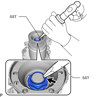
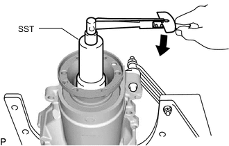
Using SST and a hammer, stake the front drive pinion companion flange front nut.
09930-00010
-
- Click here
INSTALL FRONT DRIVE SHAFT OIL SEAL LH
- Click here
INSTALL FRONT DRIVE SHAFT OIL SEAL RH
- Click here
INSTALL FRONT DIFFERENTIAL FILLER PLUG
Tip:Perform this procedure as necessary.
-
Using a 10 mm socket hexagon wrench, install a new gasket and front differential filler plug to the front differential carrier assembly.
39 N*m 398 kgf*cm 29 ft.*lbf
-
- Click here
INSTALL FRONT DIFFERENTIAL DRAIN PLUG
Tip:Perform this procedure as necessary.
-
Using a 10 mm socket hexagon wrench, install a new gasket and front differential drain plug to the front differential carrier assembly.
39 N*m 398 kgf*cm 29 ft.*lbf
-
- Click here
REMOVE FRONT DIFFERENTIAL CARRIER ASSEMBLY FROM OVERHAUL STAND
-
Remove the front differential carrier assembly from the overhaul attachment stand.
-