PROCEDURE
- Click here
AIR SUSPENSION CONTROL PROHIBITED (w/ Air Suspension)
- Click here
DRAIN TRANSFER OIL
- Click here
REMOVE PROPELLER SHAFT WITH CENTER BEARING ASSEMBLY
- Click here
REMOVE DRIVE PINION COMPANION FLANGE SUB-ASSEMBLY
-
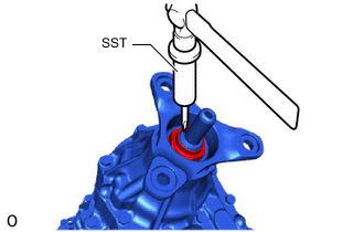
Using SST and a hammer, loosen the staked part of the transfer output shaft nut.
09930-00010 Note:
-
Completely loosen the staked part of the transfer output shaft nut.
-
Be careful not damage the threads of the No. 1 differential case.
-
Use SST with the tapered surface facing the No. 1 differential case.
-
Do not grind the end of SST with a grinder or other tool.
-
-
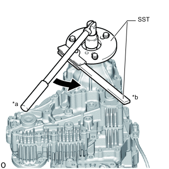
*a Turn *b Hold Using SST, hold the drive pinion companion flange sub-assembly in place.
09330-00021 09950-30012 09955-03040 Tip:Use M10 x P1.25 bolts and nuts with a length beneath the head of 35 mm to secure SST to the drive pinion companion flange.
-
Using a 30 mm socket wrench, remove the transfer output shaft nut.
-
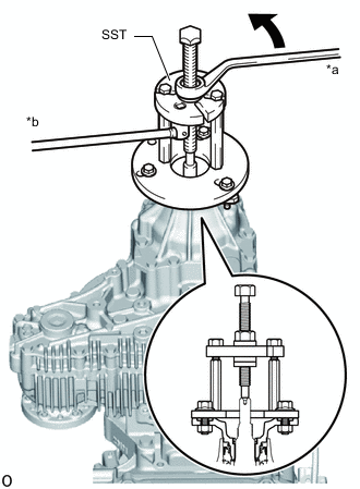
*a Turn *b Hold Using SST, remove the drive pinion companion flange sub-assembly and 2 transfer output shaft washers.
09950-30012 09951-03010 09953-03010 09954-03010 09955-03040
-
- Click here
REMOVE TRANSFER EXTENSION HOUSING OIL SEAL
-
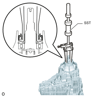
Using SST, remove the transfer extension housing oil seal.
09308-00010 Note:Be careful not to damage the surface of the transfer extension housing that contacts the transfer extension housing oil seal.
-
- Click here
INSTALL TRANSFER EXTENSION HOUSING OIL SEAL
-
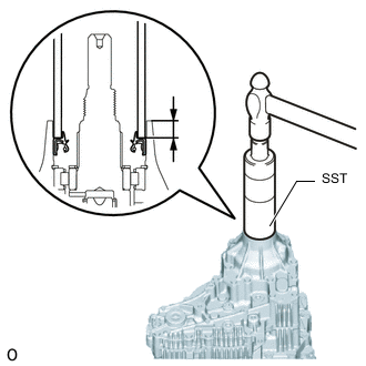
Using SST and a hammer, tap in a new transfer extension housing oil seal to the position shown in the illustration.
09316-60011 09316-00011 Standard oil seal depth 12.0 to 12.5 mm (0.4725 to 0.492 in.) from the top edge of the case -
Apply a small amount of MP grease to the lip of the transfer extension housing oil seal.
-
- Click here
INSTALL DRIVE PINION COMPANION FLANGE SUB-ASSEMBLY
-
Temporarily install the 2 transfer output shaft washers and drive pinion companion flange sub-assembly to the transfer assembly with a new transfer output shaft nut.
-
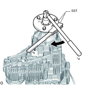
*a Turn *b Hold Using SST, hold the drive pinion companion flange sub-assembly in place.
09330-00021 09950-30012 09955-03040 Tip:Use M10 x P1.25 bolts and nuts with a length beneath the head of 35 mm to secure SST to the drive pinion companion flange.
-
Using a 30 mm socket wrench, tighten the transfer output shaft nut.
142 N*m 1448 kgf*cm 105 ft.*lbf -
Using a chisel and hammer, stake the transfer output shaft nut.
-
- Click here
INSTALL PROPELLER SHAFT WITH CENTER BEARING ASSEMBLY
- Click here
ADD TRANSFER OIL
- Click here
INSPECT TRANSFER OIL LEAK