ELECTRONIC SHIFT LEVER SYSTEM, Diagnostic DTC:P176A87
| DTC Code | DTC Name |
|---|---|
| P176A87 | Lost Communication with Fail Safe Signal (Gear Shift Control Module "A") Missing Message |
DESCRIPTION
The shift control ECU sends SBFS (fail-safe) signals to the hybrid vehicle control ECU.
| DTC No. | Detection Item | DTC Detection Condition | Trouble Area | Warning Indicate |
|---|---|---|---|---|
| P176A87 | Lost Communication with Fail Safe Signal (Gear Shift Control Module "A") Missing Message | The SBFS (fail-safe) signals sent from the shift control ECU cannot be received by the hybrid vehicle control ECU continuously for 2 seconds or more. (1 trip detection logic) |
|
|
CONFIRMATION DRIVING PATTERN
Tech Tips
After repairs have been completed, clear the DTCs and then check that the vehicle has returned to normal by performing the All Readiness check procedure.
-
Turn the power switch on (READY) and wait for 2 minutes or more.
WIRING DIAGRAM
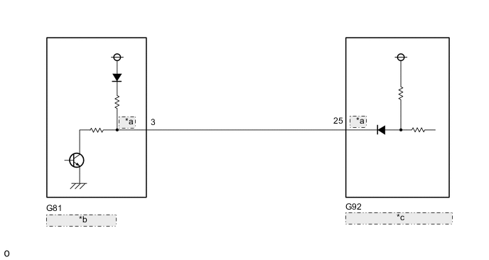
| *a | SBFS |
| *b | Shift Control ECU |
| *c | Hybrid Vehicle Control ECU |
CAUTION / NOTICE / HINT
Note
The vehicle is equipped with a sub-battery. Therefore, ensure there is no power being supplied to the vehicle when disconnecting or reconnecting the connector of the shift control ECU and when removing or installing the shift control ECU.
PROCEDURE
-
CHECK SHIFT CONTROL ECU (CHECK SBFS TERMINAL WAVEFORM)
-
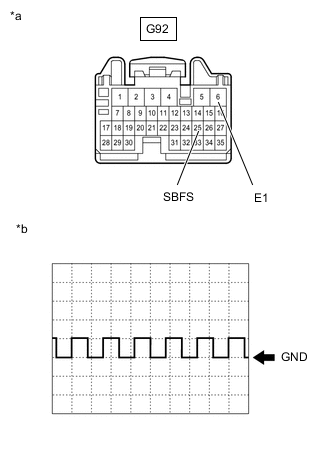
*a Front view of wire harness connector
(to Hybrid Vehicle Control ECU)
*b Waveform (Fail-safe signal) Disconnect the hybrid vehicle control ECU connector.
-
Connect an oscilloscope between the hybrid vehicle control ECU connector terminals specified in the table below.
-
Turn the power switch on (IG) and measure the waveform.
Tester Connection Condition Equipment Setting G92-25 (SBFS) - G92-6 (E1) Power switch on (IG) 10 V/DIV., 20 ms./DIV. Note
Turning the power switch on (IG) with the connector disconnected causes other DTCs to be stored. Clear the DTCs after performing this inspection.
Tech Tips
The waveforms differ when the shift control ECU is malfunctioning.
-
Turn the power switch off.
-
Reconnect the hybrid vehicle control ECU connector.
Result Proceed to OK NG
OK 
REPLACE HYBRID VEHICLE CONTROL ECU Click here
NG 
-
-
CHECK HARNESS AND CONNECTOR (SHIFT CONTROL ECU - HYBRID VEHICLE CONTROL ECU)
-
Disconnect the G81 shift control ECU connector.
-
Disconnect the G92 hybrid vehicle control ECU connector.
-
Measure the resistance according to the value(s) in the table below.
Standard Resistance (Check for Open) Tester Connection Condition Specified Condition G81-3 (SBFS) - G92-25 (SBFS) Always Below 1 Ω Standard Resistance (Check for Short) Tester Connection Condition Specified Condition G81-3 (SBFS) or G92-25 (SBFS) - Body ground and other terminals Always 10 kΩ or higher -
Reconnect the G92 hybrid vehicle control ECU connector.
-
Reconnect the G81 shift control ECU connector.
Result Proceed to OK NG
OK
REPLACE SHIFT CONTROL ECU Click here
NG
REPAIR OR REPLACE HARNESS OR CONNECTOR
-