SHIFT PADDLE SWITCH REMOVAL
CAUTION / NOTICE / HINT
The necessary procedures (adjustment, calibration, initialization, or registration) that must be performed after parts are removed, installed, or replaced during the transmission shift switch assembly removal/installation are shown below.
| Replaced Part or Performed Procedure | Necessary Procedure | Effect/Inoperative Function when Necessary Procedure not Performed | Link |
|---|---|---|---|
| Auxiliary battery terminal is disconnected/reconnected | Memorize steering angle neutral point | LKA/LDA system (for Mono camera type) | for Stereo Camera type: Click here for Mono Camera type: Click here |
| Lane control system (for Stereo camera type) | |||
| Parking support brake system*1 | |||
| Pre-collision system (for Stereo camera type) | |||
| Pre-collision system (for Mono camera type) | |||
| Adaptive high beam system | |||
Lighting system (EXT) |
|||
| Variable gear ratio steering system | |||
| Parking assist monitor system | |||
| Panoramic view monitor system | |||
| Initialize rear door sunshade system | Rear door sunshade system | ||
| Initialize power trunk lid system | Power trunk lid system | ||
| Parts between the steering wheel and tires have been removed/installed, replaced or adjusted | Perform actuator angle neutral point calibration and initialization |
|
Click here Click here
PROCEDURE
-
PRECAUTION
-
REMOVE STEERING WHEEL ASSEMBLY
-
REMOVE STEERING PAD SWITCH ASSEMBLY
-
REMOVE TRANSMISSION SHIFT SWITCH ASSEMBLY
-
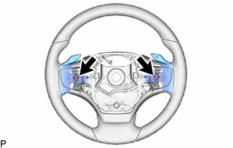
Remove the 2 screws and disconnect the 2 transmission shift switch assemblies.
-
for Transmission Shift Switch Assembly LH Side:
-
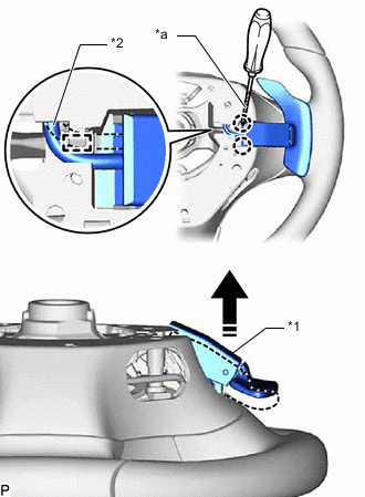
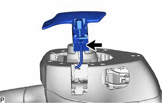
*1 Transmission Shift Switch Assembly *2 No. 1 Switch Wire *a Protective Tape 
Lift Up Vertically Using a screwdriver with its tipped wrapped with protective tape, detach the 2 claws and No. 1 switch wire from the guide and lift the transmission shift switch assembly perpendicular from the steering wheel assembly and disconnect it as shown in the illustration.
Tech Tips
Tape the screwdriver tip before use.
-
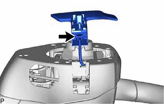
Disconnect the No. 1 switch wire connector and remove the transmission shift switch assembly.
-
-
for Transmission Shift Switch Assembly RH Side:
-
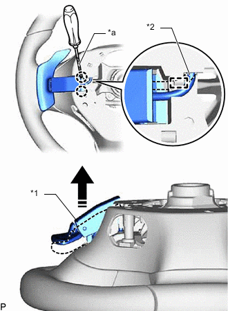
*1 Transmission Shift Switch Assembly *2 No. 1 Switch Wire *a Protective Tape Lift Up Vertically Using a screwdriver with its tipped wrapped with protective tape, detach the 2 claws and No. 1 switch wire from the guide and lift the transmission shift switch assembly perpendicular from the steering wheel assembly and disconnect it as shown in the illustration.
Tech Tips
Tape the screwdriver tip before use.
-
Disconnect the No. 1 switch wire connector and remove the transmission shift switch assembly.
-
-
-
REMOVE NO. 1 SWITCH WIRE
-
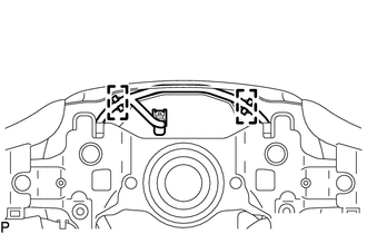
Disconnect the 2 guides and remove the No. 1 switch wire from the lower steering wheel boss cover.
-