CAUTION / NOTICE / HINT
Do not turn the power switch on (READY) until the oil pump motor controller installation is completed.
PROCEDURE
- Click here
INSTALL OIL PUMP MOTOR CONTROLLER
Note:If the oil pump motor controller has been struck or dropped, replace it.
-
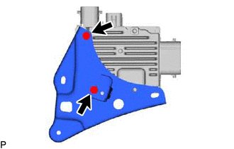
Install the oil pump motor controller bracket to the oil pump motor controller with the 2 bolts.
6.0 N*m 61 kgf*cm 53 in.*lbf -
Install the oil pump motor controller bracket to the oil pump motor controller with the 2 bolts.
6.0 N*m 61 kgf*cm 53 in.*lbf -
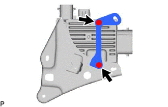
Install the oil pump motor controller with bracket with the 2 nuts.
8.5 N*m 87 kgf*cm 75 in.*lbf
-
- Click here
CONNECT CONNECTOR
-
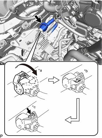
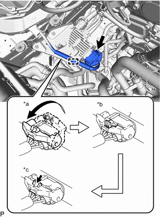
*a Raise the lock lever *b Securely lock the claw *c Push in the lock Connect the connector and securely lock the lock lever as shown in the illustration.
Note:
-
Be sure to securely lock the claw of the connector.
-
Push the connector all the way in and lock the lock lever.
Tip:When the connector is pushed all the way in, the lock lever will move slightly towards the lock position.
-
-
Push the lock into the lock lever to securely lock the lock lever of the connector.
Note:Securely lock the lock lever of the connector.
-
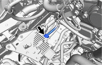
Connect the connector to the oil pump motor controller.
-
*a Raise the lock lever *b Securely lock the claw *c Push in the lock Connect the connector and securely lock the lock lever as shown in the illustration.
Note:
-
Be sure to securely lock the claw of the connector.
-
Push the connector all the way in and lock the lock lever.
Tip:When the connector is pushed all the way in, the lock lever will move slightly towards the lock position.
-
-
Push the lock into the lock lever to securely lock the lock lever of the connector.
Note:Securely lock the lock lever of the connector.
-
Attach the wire harness clamp to the oil pump motor controller bracket.
-
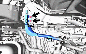
Attach the 2 clamps and connect the ground wire.
-
Install the 2 bolts.
10 N*m 102 kgf*cm 7 ft.*lbf
-
- Click here
INSTALL AIR CLEANER ASSEMBLY
-
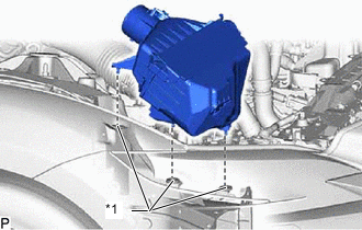
*1 Air Cleaner Support Install the air cleaner assembly to the 3 air cleaner supports.
-
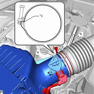
*a Protrusion *b Cutout *c Stopper Align the protrusion of the air cleaner assembly with the cutout of the air cleaner hose assembly, and connect the air cleaner hose assembly to the air cleaner assembly.
-
Tighten while pressing the hose clamp against the stopper on the air cleaner hose assembly.
4.0 N*m 41 kgf*cm 35 in.*lbf -
Connect the intake mass air flow meter connector.
-
Attach the wire harness clamp.
-
- Click here
INSTALL NO. 1 AIR CLEANER INLET
- Click here
INSTALL RADIATOR SUPPORT TO CROSS MEMBER BRACE SUB-ASSEMBLY RH
- Click here
INSTALL LOWER RADIATOR AIR DEFLECTOR
- Click here
INSTALL RADIATOR COVER PLATE
- Click here
CONNECT CABLE TO NEGATIVE AUXILIARY BATTERY TERMINAL