HYBRID VEHICLE TRANSMISSION INSTALLATION
CAUTION / NOTICE / HINT
CAUTION:
As the engine assembly with transmission is extremely heavy, the engine lifter may suddenly drop if the instructions listed in the repair manual are not followed.
Therefore, always follow the instructions listed in the repair manual when performing this procedure.
PROCEDURE
-
INSTALL AUTOMATIC TRANSMISSION CASE COVER
-
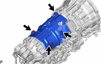
Install the automatic transmission case cover with the 4 bolts.
- Torque:
- 5.4 N*m { 55 kgf*cm, 48 in.*lbf }
-
-
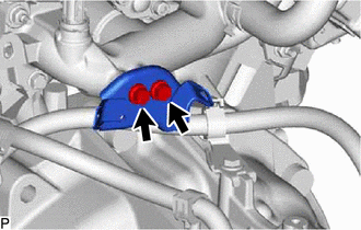
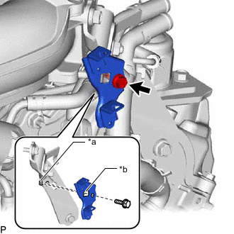
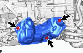
INSTALL DYNAMIC DAMPER
Note
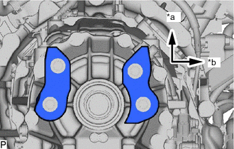
*a Upper Side *b RH Side Check the installation direction of the dynamic damper before installing it.
-
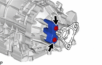
Using a T40 ''TORX'' socket wrench, install the dynamic damper with the 2 bolts.
- Torque:
- 20 N*m { 204 kgf*cm, 15 ft.*lbf }
-
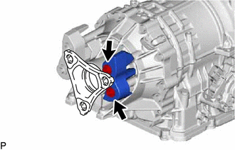
Using a T40 ''TORX'' socket wrench, install the dynamic damper with the 2 bolts.
- Torque:
- 20 N*m { 204 kgf*cm, 15 ft.*lbf }
-
-
INSTALL BRACKET
-
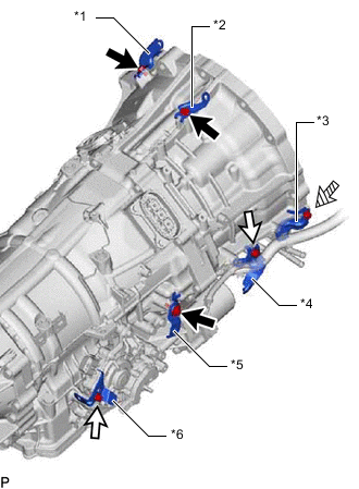
*1 No. 3 Wiring Harness Clamp Bracket *2 No. 2 Wiring Harness Clamp Bracket *3 Wiring Harness Clamp Bracket *4 No. 1 Wiring Harness Clamp Bracket *5 Transmission Oil Pump Insulator Bracket *6 No. 2 Heat Insulator Bracket 
Bolt A 
Bolt B 
Bolt C Install the 6 brackets with the 6 bolts.
- Torque:
- for bolt A
- 7.0 N*m { 71 kgf*cm, 62 in.*lbf }
- for bolt B
- 8.0 N*m { 82 kgf*cm, 71 in.*lbf }
- for bolt C
- 10 N*m { 102 kgf*cm, 7 ft.*lbf }
-
-
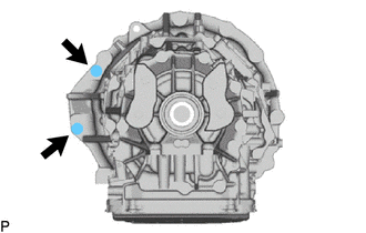
INSTALL HYBRID VEHICLE TRANSMISSION ASSEMBLY
-
Make sure that the knock pins are installed on the engine assembly.
-
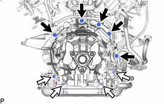
Bolt A Bolt B Install the hybrid vehicle transmission assembly to the engine assembly with the 9 bolts as shown in the illustration.
- Torque:
- for bolt A
- 71 N*m { 724 kgf*cm, 52 ft.*lbf }
- for bolt B
- 37 N*m { 377 kgf*cm, 27 ft.*lbf }
CAUTION:
-
Do not raise the hybrid vehicle transmission assembly more than necessary.
-
Make sure to confirm the center of the gravity of the hybrid vehicle transmission assembly when supporting it.
Note
-
Before tightening, check that the contact surfaces of the engine assembly and hybrid vehicle transmission assembly are in close contact.
-
Do not apply grease either to the splines or input shaft.
Tech Tips
Bolt Bolt Length A 50 mm (1.97 in.) B 43 mm (1.69 in.)
-
-
INSTALL REAR ENGINE MOUNTING INSULATOR
-
Install the rear engine mounting insulator with the 4 bolts.
- Torque:
- 34 N*m { 347 kgf*cm, 25 ft.*lbf }
-
-
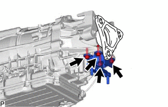
INSTALL ENGINE REAR MOUNTING MEMBER
-
Install the engine rear mounting member with the 3 nuts.
- Torque:
- 34 N*m { 347 kgf*cm, 25 ft.*lbf }
-
Bolt Nut and Spring Washer Connect the No. 2 parking lock release cable assembly to the shift control actuator assembly with the nut, spring washer and 2 bolts.
- Torque:
- for bolt
- 8.0 N*m { 82 kgf*cm, 71 in.*lbf }
- for nut
- 12.7 N*m { 130 kgf*cm, 9 ft.*lbf }
-
-
INSTALL FLYWHEEL HOUSING SIDE COVER
-
Install the flywheel housing side cover to the engine assembly as shown in the illustration.
-
-
INSTALL STARTER HOLE INSULATOR
-
Install the starter hole insulator with the 2 bolts.
- Torque:
- 58 N*m { 591 kgf*cm, 43 ft.*lbf }
-
-
INSTALL OIL COOLER WITHOUT HOSE TUBE SUB-ASSEMBLY
-
Install the No. 1 oil cooler outlet hose to the oil cooler without hose tube sub-assembly and oil cooler union sub-assembly, and slide the 2 clips to secure the hose.
Note
-
When connecting the No. 1 oil cooler outlet hose, align with the colors and positions of the paint mark before connecting.
-
After connecting the No. 1 oil cooler outlet hose, check that the hose is not twisted.
-
-
Install the No. 1 oil cooler inlet hose to the oil cooler without hose tube sub-assembly and oil cooler union sub-assembly, and slide the 2 clips to secure the hose.
Note
-
When connecting the No. 1 oil cooler inlet hose, align with the colors and positions of the paint mark before connecting.
-
After connecting the No. 1 oil cooler inlet hose, check that the hose is not twisted.
-
-
Install the No. 2 oil cooler outlet hose to the oil cooler without hose tube sub-assembly, and slide the clip to secure the hose.
Note
-
When connecting the No. 2 oil cooler outlet hose, align with the colors and positions of the paint mark before connecting.
-
After connecting the No. 2 oil cooler outlet hose, check that the hose is not twisted.
-
-
Install the No. 2 oil cooler inlet hose to the oil cooler without hose tube sub-assembly, and slide the clip to secure the hose.
Note
-
When connecting the No. 2 oil cooler inlet hose, align with the colors and positions of the paint mark before connecting.
-
After connecting the No. 2 oil cooler inlet hose, check that the hose is not twisted.
-
-
Temporarily install the oil cooler union sub-assembly with the 2 union bolts, 4 new gaskets and 2 bolts (B).
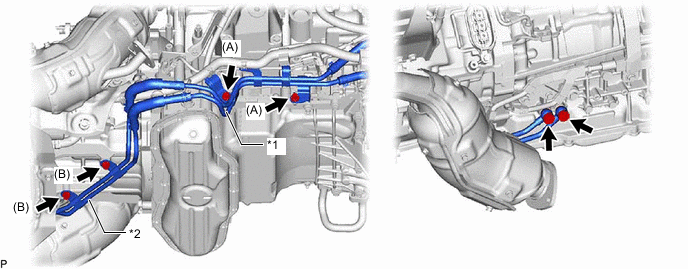
*1 Oil Cooler without Hose Tube Sub-assembly *2 Oil Cooler Union Sub-assembly -
Temporarily install the oil cooler without hose tube sub-assembly with the 2 bolts (A).
-
Tighten the 2 union bolts and 4 bolts.
- Torque:
- for union bolt
- 27.5 N*m { 280 kgf*cm, 20 ft.*lbf }
- for bolt
- 22 N*m { 224 kgf*cm, 16 ft.*lbf }
-
Connect the 9 wire harness clamps.
-
Connect the oil pump thermistor connector.
-
Connect the No. 2 oil cooler inlet hose to the motor cooling cooler, and slide the clip to secure the hose.
Note
-
When connecting the No. 2 oil cooler inlet hose, align with the colors and positions of the paint mark before connecting.
-
After connecting the No. 2 oil cooler inlet hose, check that the hose is not twisted.
-
Do not deform the motor cooling cooler.
-
-
-
INSTALL WIRE HARNESS CLAMP BRACKET
-
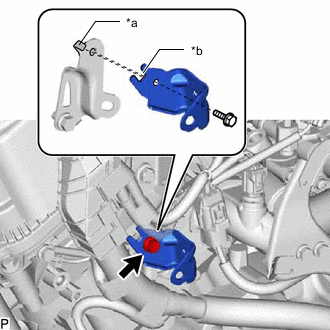
*a Protrusion *b Cutout Install the wire harness clamp bracket with the bolt.
- Torque:
- 8.0 N*m { 82 kgf*cm, 71 in.*lbf }
Tech Tips
Align the cutout with the protrusion as shown in the illustration.
-
-
INSTALL ENGINE MOTOR CABLE CLAMP BRACKET
-
for LHD:
-
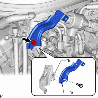
*a Protrusion *b Cutout Install the engine motor cable clamp bracket with the bolt.
- Torque:
- 8.0 N*m { 82 kgf*cm, 71 in.*lbf }
Tech Tips
Align the cutout with the protrusion as shown in the illustration.
-
Install the engine motor cable clamp bracket with the 2 bolts.
- Torque:
- 8.0 N*m { 82 kgf*cm, 71 in.*lbf }
-
*a Protrusion *b Hole Install the engine motor cable clamp bracket with the bolt.
- Torque:
- 8.0 N*m { 82 kgf*cm, 71 in.*lbf }
Tech Tips
Align the hole with the protrusion as shown in the illustration.
-
-
for RHD:
-
Install the engine motor cable clamp bracket with the 2 bolts.
- Torque:
- 8.0 N*m { 82 kgf*cm, 71 in.*lbf }
-
*a Protrusion *b Cutout Install the engine motor cable clamp bracket with the bolt.
- Torque:
- 8.0 N*m { 82 kgf*cm, 71 in.*lbf }
Tech Tips
Align the cutout with the protrusion as shown in the illustration.
-
-
-
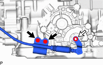
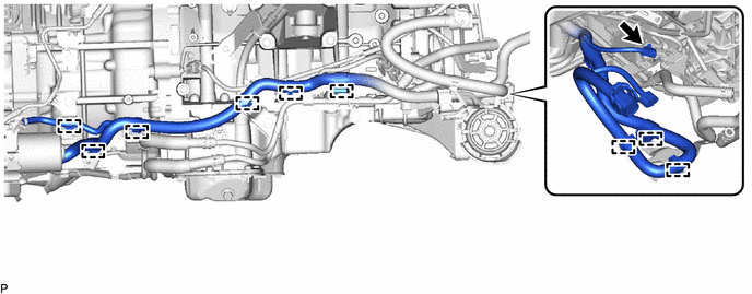
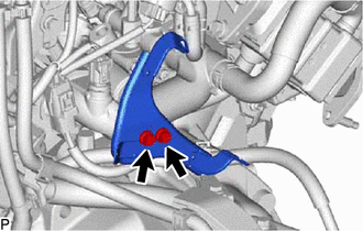
INSTALL NO. 1 TRANSMISSION BREATHER ASSEMBLY
-
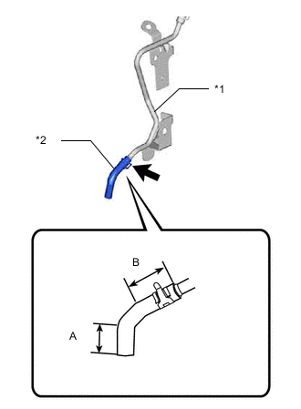
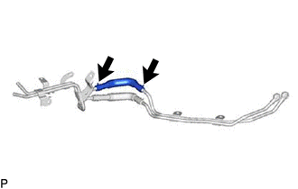
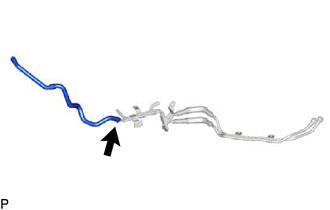
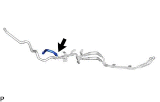
*1 No. 1 Transmission Breather Assembly *2 Transmission Breather Hose Install the transmission breather hose to the No. 1 transmission breather assembly, and slide the clip to secure the hose.
Note
-
Install the long side of the transmission breather hose to the breather tube.
Side B of the transmission breather hose is longer than side A.
-
Install the clip facing upwards so that it does not interfere with other parts when the No. 1 transmission breather assembly is installed to the hybrid vehicle transmission assembly.
-
Check that the clip is not interfering with other parts after installing the No. 1 transmission breather assembly to the hybrid vehicle transmission.
-
-
Bolt A Bolt B Install the No. 1 transmission breather assembly with the 2 bolts and connect the 3 clamps.
- Torque:
- for bolt A
- 7.0 N*m { 71 kgf*cm, 62 in.*lbf }
- for bolt B
- 16 N*m { 163 kgf*cm, 12 ft.*lbf }
-
-
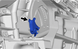
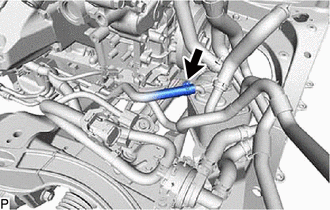
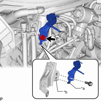
INSTALL NO. 2 TRANSMISSION BREATHER ASSEMBLY
-
Coat a new O-ring with Toyota Genuine ATF WS.
-
Install the O-ring to the No. 2 transmission breather assembly.
-
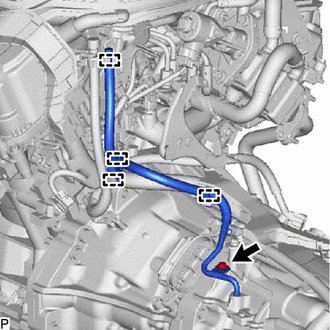
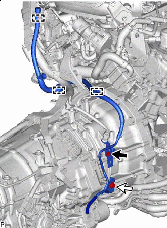
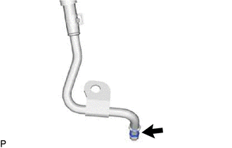
Install the No. 2 transmission breather assembly with the bolt and connect the 4 clamps.
- Torque:
- 7.0 N*m { 71 kgf*cm, 62 in.*lbf }
-
-
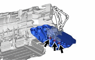
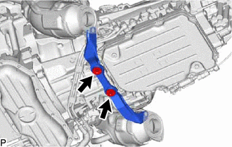
INSTALL TRANSMISSION OIL PUMP INSULATOR
-
Install the transmission oil pump insulator with the 3 bolts.
- Torque:
- 8.0 N*m { 82 kgf*cm, 71 in.*lbf }
-
-
CONNECT WIRE HARNESS
-
Connect the wire harness to the hybrid vehicle transmission assembly with the 6 bolts and connect the 5 wire harness clamps.
- Torque:
- 10 N*m { 102 kgf*cm, 7 ft.*lbf }
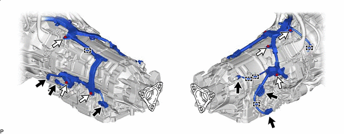
Wire Harness Connector Bolt -
Connect the 6 wire harness connectors.
-
-
INSTALL MOTOR CABLE
-
INSTALL GENERATOR CABLE
-
INSTALL EXHAUST MANIFOLD ASSEMBLY RH
-
INSTALL EXHAUST MANIFOLD ASSEMBLY LH
-
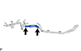
INSTALL NO. 1 EGR PIPE
-
INSTALL NO. 1 EXHAUST PIPE SUPPORT BRACKET SUB-ASSEMBLY
-
Install the No. 1 exhaust pipe support bracket sub-assembly with the 2 bolts.
- Torque:
- 43 N*m { 438 kgf*cm, 32 ft.*lbf }
-
-
INSTALL ENGINE ASSEMBLY WITH HYBRID VEHICLE TRANSMISSION
-
PERFORM INITIALIZATION
-
PERFORM RESOLVER INITIALIZATION
-
PERFORM RESET MEMORY
If the hybrid vehicle transmission assembly is replaced, initialize the learning value of the transmission.
-
CHECK VEHICLE HEIGHT CONTROL (w/ Air Suspension)