HYBRID TRANSMISSION REAR OIL SEAL REPLACEMENT

PROCEDURE
-
AIR SUSPENSION CONTROL PROHIBITED (w/ Air Suspension)
-
REMOVE PROPELLER WITH CENTER BEARING SHAFT ASSEMBLY
-
REMOVE FLANGE YOKE ASSEMBLY
-
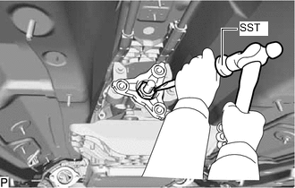
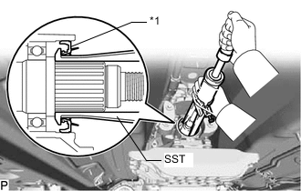
Using SST and a hammer, loosen the staked part of the lock nut.
- SST
- 09930-00010
Note
-
Be sure to use SST with the tapered surface facing the shaft.
-
Do not grind the tip of SST with a grinder or other device.
-
Completely loosen the staked part of the lock nut when removing it.
-
Do not damage the threads of the output shaft.
-
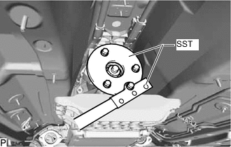
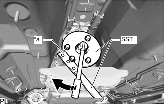
Using SST, secure the flange yoke assembly.
- SST
- 09330-00021
- 09950-30012 ( 09955-03040 )
Tech Tips
Use a M8 x 1.25 bolt with an under head length of 45 mm (1.77 in.) to secure bolt.
-
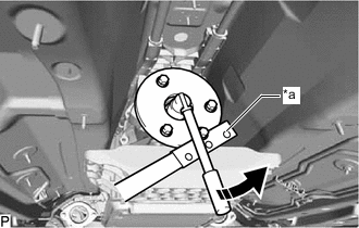
*a Hold 
Turn Using a 30 mm deep socket wrench, remove the lock nut from the flange yoke assembly.
-
Remove the flange yoke assembly from the output shaft.
-
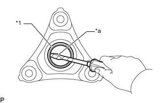
*1 Flange Yoke Type V Oil Seal *a Protective Tape Using a screwdriver with its tip wrapped with protective tape, remove the flange yoke type V oil seal from the flange yoke assembly.
Note
When removing the flange yoke type V oil seal, make sure not to damage the flange yoke assembly.
-
-
REMOVE EXTENSION HOUSING TYPE T OIL SEAL
-
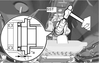
*1 Extension Housing Type T Oil Seal Using SST, remove the extension housing type T oil seal from the extension housing sub-assembly.
- SST
- 09308-36010
Note
When removing the extension housing type T oil seal, make sure not to damage the output shaft or extension housing sub-assembly.
-
-
INSTALL EXTENSION HOUSING TYPE T OIL SEAL
-
Coat the lip of a new extension housing type T oil seal with a small amount of MP grease.
-
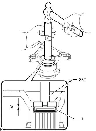
*a 3.3 to 3.7 mm (0.130 to 0.146 in.) Using SST and hammer, install the extension housing type T oil seal to the extension housing sub-assembly
- SST
- 09316-60012 ( 09316-00011, 09316-00041 )
- 09502-12010
Extension Housing Type T Oil Seal Installation Depth 3.3 to 3.7 mm (0.130 to 0.146 in.) Note
-
Keep the extension housing type T oil seal lip free of foreign matter.
-
Do not install the extension housing type T oil seal at an angle.
-
When installing the extension housing type T oil seal to the extension housing sub-assembly, do not damage the extension housing type T oil seal.
-
-
INSTALL FLANGE YOKE ASSEMBLY
-
*1 Flange Yoke Type V Oil Seal *a 0 to 0.3 mm (0 to 0.0118 in.) Using SST and a hammer, install a new flange yoke type V oil seal to the flange yoke assembly.
- SST
- 09950-60011 ( 09951-00410 )
- 09950-70010 ( 09951-07100 )
Flange Yoke Type V Oil Seal Installation Depth 0 to 0.3 mm (0 to 0.0118 in.) Note
-
Keep the flange yoke type V oil seal lip free of foreign matter.
-
Do not install the flange yoke type V oil seal at an angle.
-
When installing the flange yoke type V oil seal to the flange yoke assembly, do not damage the flange yoke type V oil seal.
-
Temporarily install the flange yoke assembly to the output shaft with a new lock nut.
-
*a Hold Turn Using SST, secure the flange yoke assembly.
- SST
- 09330-00021
- 09950-30012 ( 09955-03040 )
Tech Tips
Use a M8 x 1.25 bolt with an under head length of 45 mm (1.77 in.) to secure SST.
-
Using a 30 mm deep socket wrench, tighten the lock nut.
- Torque:
- 135 N*m { 1377 kgf*cm, 100 ft.*lbf }
-
Using a chisel and hammer, stake the lock nut.
-
-
INSTALL PROPELLER WITH CENTER BEARING SHAFT ASSEMBLY
-
ADJUST TRANSMISSION FLUID