Click here
-
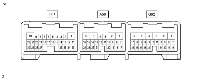
*a TERMINALS OF SHIFT CONTROL ECU - - CHECK SHIFT CONTROL ECU
Terminal No. (Symbol) Input/Output Wiring Color Terminal Description Condition Specified Condition A50-1 (MWA) - G82-6 (E01) Output L - W-B Parking lock motor signal Power switch on (IG) 7.5 to 15.4 V A50-2 (MVA) - G82-6 (E01) Output R - W-B Parking lock motor signal Power switch on (IG) 7.5 to 15.4 V A50-5 (MUA) - G82-6 (E01) Output B - W-B Parking lock motor signal Power switch on (IG) 7.5 to 15.4 V A50-7 (SS) - Body ground - - Shield line Always Below 1 Ω A50-12 (BMA1) - G81-1 (E1) Output G - W-B P CON MTR relay operation signal Power switch off → Power switch on (IG) 7.5 to 15.4 V → Below 1 V A50-16 (RS) - Body ground - - Shield line Always Below 1 Ω A50-17 (E2NS) - G81-1 (E1) Input G - W-B Range sensor ground Always 0.4 V or less A50-18 (NS2) - A50-17 (E2NS) Input R - G Range sensor signal Power switch on (IG), shift state park (P) 0.5 to 4.5 V A50-19 (VCNS) - A50-17 (E2NS) Output B - G Power source of range sensor Power switch on (IG) 4.5 to 5.5 V A50-20 (NS1) - A50-17 (E2NS) Input W - G Range sensor signal Power switch on (IG), shift state park (P) 0.5 to 4.5 V A50-21 (RB) - A50-24 (E2) Input G - W Rotation angle sensor signal Power switch off → Power switch on (IG) 0.4 V or less → 4.9 V or higher Power switch on (IG), changing the shift state between park (P) and neutral (N) Pulse generation (see waveform 1) A50-22 (VC) - A50-24 (E2) Output R - W Power source of rotation angle sensor Power switch on (IG) 4.5 to 5.5 V A50-23 (RA) - A50-24 (E2) Input B - W Rotation angle sensor signal Power switch off → Power switch on (IG) 0.4 V or less → 4.9 V or higher Power switch on (IG), changing the shift state between park (P) and neutral (N) Pulse generation (see waveform 1) A50-24 (E2) - G81-1 (E1) Output W - W-B Rotation angle sensor ground Always 0.4 V or less G81-1 (E1) - Body ground - W-B - - Ground Always Below 1 Ω G81-3 (SBFS) - G81-1 (E1) Output BE - W-B Fail-safe signal Power switch on (IG) Pulse generation (see waveform 2) G81-5 (CA2L) - G81-1 (E1) Input/Output W - W-B CAN communication signal Power switch on (IG) Pulse generation (see waveform 3) G81-6 (CA2H) - G81-1 (E1) Input/Output P - W-B CAN communication signal Power switch on (IG) Pulse generation (see waveform 3) G81-8 (CA1L) - G81-1 (E1) Input/Output W - W-B CAN communication signal Power switch on (IG) Pulse generation (see waveform 4) G81-9 (CA1H) - G81-1 (E1) Input/Output Y - W-B CAN communication signal Power switch on (IG) Pulse generation (see waveform 4) G81-10 (BUB) - G81-1 (E1) Input G - W-B Sub-battery power supply Power switch on (IG)*1 8 to 15.4 V G81-11 (EC) - Body ground - W-B - - Ground Always Below 1 Ω G81-13 (PPOS) - G81-1 (E1) Output LG - W-B Shift state signal Power switch on (IG), shift state park (P) Pulse generation (see waveform 5) G81-15 (BL) - G81-1 (E1) Output R - W-B Back-up light relay operation signal Shift state reverse (R) 7.25 to 14.65 V Shift state not reverse (R) 1 V or less G81-18 (ACC) - G81-1 (E1) Input LA-R - W-B ACC power supply Power switch on (ACC) 6 V or higher G81-20 (IGCT) - G81-1 (E1) Input LA-W - W-B IGCT power supply Power switch on (IG) 6 V or higher G81-22 (BUBI) - G81-1 (E1) Input P - W-B Sub-battery condition signal Power switch on (IG) Pulse generation (see waveform 6) G81-24 (BMA2) - G81-1 (E1) Output V - W-B P CON MTR2 relay operation signal Power switch on (IG)*2 7.5 to 15.4 V G81-27 (IG2) - G81-1 (E1) Input B - W-B IG2 power supply Power switch on (IG) 6 V or higher G81-29 (BUBO) - G81-1 (E1) Output W - W-B Backup request signal Power switch on (IG) Pulse generation (see waveform 7) G82-1 (BATT) - G81-1 (E1) Input G - W-B Auxiliary battery power supply Always 8 to 15.4 V G82-4 (E03) - Body ground - W-B - - Ground Always Below 1 Ω G82-5 (E02) - Body ground - W-B - - Ground Always Below 1 Ω G82-6 (E01) - Body ground - W-B - - Ground Always Below 1 Ω G82-10 (P1) - G81-1 (E1) Input SB - W-B P position switch signal Power switch on (IG), P position switch not operated 5.8 V or higher Power switch on (IG), P position switch being pushed and held 2.47 to 5.8 V G82-11 (ACCI) - G81-1 (E1) Output P - W-B Power source of shift position indicator Power switch off → Power switch on (ACC) 1 V or less → 8 to 15.4 V G82-12 (INDP) - G81-1 (E1) Output B - W-B Shift position indicator signal (P) Shift state park (P) 1 V or less Shift state not park (P) 8 to 15.4 V G82-13 (INDM) - G81-1 (E1) Output L - W-B Shift position indicator signal (M) Shift state manual (M) 1 V or less Shift state not manual (M) 8 to 15.4 V G82-14 (INDD) - G81-1 (E1) Output R - W-B Shift position indicator signal (D) Shift state drive (D) 1 V or less Shift state not drive (D) 8 to 15.4 V G82-15 (INDN) - G81-1 (E1) Output G - W-B Shift position indicator signal (N) Shift state neutral (N) 1 V or less Shift state not neutral (N) 8 to 15.4 V G82-16 (INDR) - G81-1 (E1) Output W - W-B Shift position indicator signal (R) Shift state reverse (R) 1 V or less Shift state not reverse (R) 8 to 15.4 V G82-17 (E12) - Body ground - W-B - - Ground Always Below 1 Ω G82-18 (STP) - G81-1 (E1) Input R - W-B Stop light switch signal Brake pedal depressed 7.17 V or higher Brake pedal released 2 V or less G82-19 (VSI1) - G82-24 (E2X1) Input B - LG Shift lever position signal Power switch on (READY), shift lever in home position 3.634 to 4.226 V Power switch on (READY), shift lever in D 1.366 to 1.923 V Power switch on (READY), shift lever in N 0.774 to 1.366 V Power switch on (READY), shift lever in R 0.3 to 0.774 V Power switch on (READY), shift lever in M 2.5 to 3.634 V G82-20 (VCX1) - G82-24 (E2X1) Output L - LG Power source of shift lever position sensor Power switch on (IG) 4.5 to 5.5 V G82-21 (VSI2) - G82-24 (E2X1) Input W - LG Shift lever position signal Power switch on (READY), shift lever in home position 3.084 to 3.676 V Power switch on (READY), shift lever in D 2.08 to 2.5 V Power switch on (READY), shift lever in N 1.324 to 2.08 V Power switch on (READY), shift lever in R 0.3 to 1.324 V Power switch on (READY), shift lever in M 2.5 to 3.084 V G82-22 (VCX2) - G82-26 (E2X2) Output GR - SB Power source of shift lever position sensor Power switch on (IG) 4.5 to 5.5 V G82-23 (VSI3) - G82-26 (E2X2) Input V - SB Shift lever position signal Power switch on (READY), shift lever in home position 1.324 to 1.916 V Power switch on (READY), shift lever in D 3.676 to 4.75 V Power switch on (READY), shift lever in N 2.92 to 3.676 V Power switch on (READY), shift lever in R 2.5 to 2.92 V Power switch on (READY), shift lever in M 0.3 to 1.324 V G82-24 (E2X1) - G81-1 (E1) Input LG - W-B Shift lever position sensor ground Power switch on (IG) 0.4 V or less G82-25 (VSI4) - G82-26 (E2X2) Input P - SB Shift lever position signal Power switch on (READY), shift lever in home position 0.774 to 1.366 V Power switch on (READY), shift lever in D 4.226 to 4.75 V Power switch on (READY), shift lever in N 3.634 to 4.226 V Power switch on (READY), shift lever in R 3.077 to 3.634 V Power switch on (READY), shift lever in M 0.3 to 0.774 V G82-26 (E2X2) - G81-1 (E1) Input SB - W-B Shift lever position sensor ground Power switch on (IG) 0.4 V or less *1: Power is supplied from the sub-battery module assembly for only 5 seconds after the power switch is turned on (IG). Therefore, measure the voltage during that time.
*2: With the power switch on (IG), disconnect the cable from the negative (-) auxiliary battery terminal and check that the voltage level changes.
-
OSCILLOSCOPE WAVEFORMS
Tip:Oscilloscope waveform samples are provided here for reference only. Noise and fluctuating waveforms have been omitted.
-
Waveform 1 (Rotation angle sensor signal)
Item Contents Terminal CH1: RA - E2
CH2: RB - E2
Equipment setting 2 V/DIV., 200 ms./DIV. Condition Power switch on (IG), changing the shift state between park (P) and neutral (N) Tip:When changing the shift state from park (P) to neutral (N), or neutral (N) to park (P) with the power switch on (IG), a waveform will be generated for up to 1.5 seconds.
-

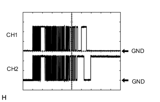
Waveform 2 (Fail-safe signal)
Item Contents Terminal SBFS - E1 Equipment setting 10 V/DIV., 20 ms./DIV. Condition Power switch on (IG) Tip:The waveforms differ when the shift control ECU is malfunctioning.
-
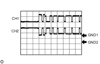
Waveform 3 (CAN communication signal)
Item Contents Terminal CH1: CA2H - E1
CH2: CA2L - E1
Equipment setting 1 V/DIV., 10 μs./DIV. Condition Power switch on (IG) Tip:The waveform will vary depending on the content of the digital communication (digital signal).
-
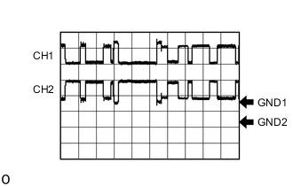
Waveform 4 (CAN communication signal)
Item Contents Terminal CH1: CA1H - E1
CH2: CA1L - E1
Equipment setting 1 V/DIV., 10 μs./DIV. Condition Power switch on (IG) Tip:The waveform will vary depending on the content of the digital communication (digital signal).
-
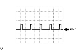
Waveform 5 (Shift state signal)
Item Contents Terminal PPOS - E1 Equipment setting 10 V/DIV., 10 ms./DIV. Condition Power switch on (IG), shift state park (P) Tip:The waveform will vary depending on the shift state.
-
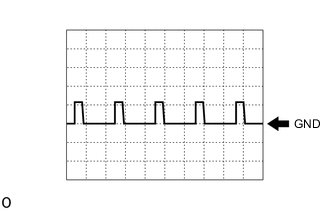
Waveform 6 (Sub-battery condition signal)
Item Contents Terminal BUBI - E1 Equipment setting 10 V/DIV., 10 ms./DIV. Condition Power switch on (IG) Tip:The duty ratio changes according to the vehicle condition.
-
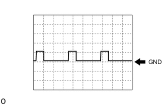
Waveform 7 (Backup request signal)
Item Contents Terminal BUBO - E1 Equipment setting 10 V/DIV., 10 ms./DIV. Condition Power switch on (IG) Tip:The duty ratio changes according to the vehicle condition.
-