PROCEDURE
- Click here
ADJUST STANDARD VEHICLE HEIGHT (for 2WD)
- Click here
ADJUST STANDARD VEHICLE HEIGHT (for AWD)
- Click here
PREPARATION FOR MILLIMETER WAVE RADAR SENSOR ASSEMBLY ADJUSTMENT
-
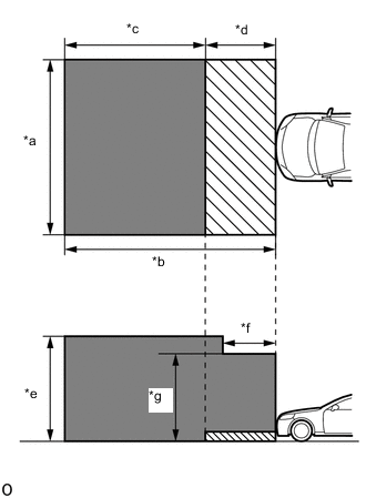
*a 5 m (16.4 ft.) *b 6 m (19.7 ft.) *c 4 m (13.1 ft.) *d 2 m (6.56 ft.) *e 3 m (9.84 ft.) *f 1.5 m (4.92 ft.) *g 2.5 m (8.2 ft.) 
Do not place any metal objects in this area 
Do not place metal objects with a height of more than 50 mm (1.97 in.) in this area for Stereo Camera Type:
-
Park the vehicle on a level surface where the area in front of the vehicle shown in the illustration is free of metal objects.
Tip:Metal objects that have a height of 50 mm (1.97 in.) or less do not affect adjustment within 2 m (6.56 ft.) from the front of the vehicle.
-
-
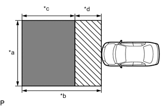
*a 5 m (16.4 ft.) *b 6 m (19.7 ft.) *c 4 m (13.1 ft.) *d 2 m (6.56 ft.) Do not place any metal objects in this area Do not place metal objects with a height of more than 50 mm (1.97 in.) in this area for Mono Camera Type:
-
Park the vehicle on a level surface where the area in front of the vehicle shown in the illustration is free of metal objects.
Tip:Metal objects with a height of 50 mm (1.97 in.) or less placed within the area shown in the illustration will not affect the adjustment.
-
-
Check the levelness of the ground.
-
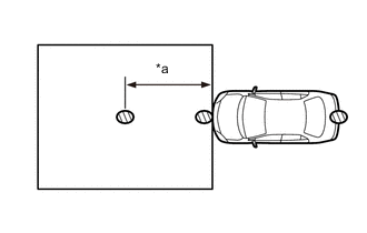
*a 3 m (9.84 ft.) Levelness Check Point Check the levelness of the ground at the 3 points shown in the illustration.
-
Place the level on each levelness check point and check that the air bubble of the level is centered.
-
-
Adjust the tire inflation pressure to the specified pressure.
-
Clean the radiator grille (or front panel) emblem or millimeter wave radar sensor assembly.
-
Visually inspect the front of the vehicle.
Tip:Confirm that there is no damage or deformation.
-
Visually inspect the front bumper assembly, radiator grille and stays.
Tip:Confirm that there is no damage or deformation.
-
- Click here
ADJUST MILLIMETER WAVE RADAR SENSOR ASSEMBLY VERTICALLY AND HORIZONTALLY (for Stereo Camera Type)
-
Adjust SST (reflector) height.
-
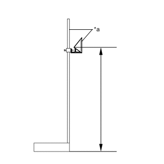
*a SST (reflector) Adjust SST (reflector) so that the center of SST (reflector) is the same height as the millimeter wave radar sensor assembly.
Tip:Make sure to align the center of SST (reflector) with the millimeter wave radar sensor assembly (the center of the emblem).
Reference Value about 600 mm (1.97 ft.) 09870-60000 09870-60010 09870-60040
-
-
Place SST (reflector).
-
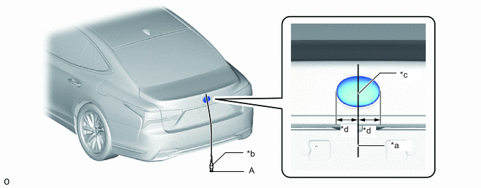
*a String *b Weight *c Center *d Bilateral Symmetry Hang a weight with a pointed tip from the center of the rear emblem, and mark the rear center point of the vehicle (point A) on the ground.
Tip:Lightly flick the string with your fingers several times to confirm that the string is perpendicular to the ground.
-
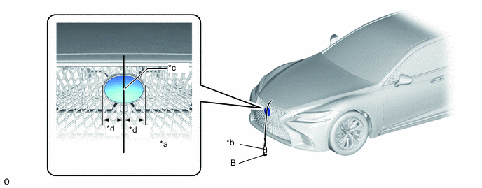
*a String *b Weight *c Center *d Bilateral Symmetry Hang a weight with a pointed tip from the center of the radiator grille (or front panel) emblem, and mark the front center point of the vehicle (point B) on the ground.
Tip:Lightly flick the string with your fingers several times to confirm that the string is perpendicular to the ground.
-
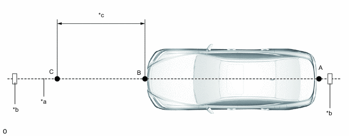
*a String *b Tape *c 3000 mm (9.84 ft.) - - Using tape and a string, create a line that connects point B to point A and extends at least 3000 mm (9.84 ft.) beyond the front center point of the vehicle.
Tip:
-
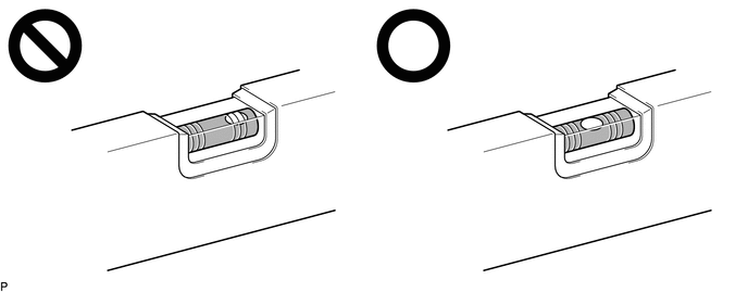
Make sure the string is taut when securing it with tape.
-
Lightly flick the string with your fingers several times to confirm that the string is aligned with point B.
-
-
Mark point C (SST (reflector) placement position) at a position 3000 mm (9.84 ft.) from point B.
-
Place SST (reflector) at point C.
-
-
Front Beam Axis Adjustment:
Note:
-
Close all of the doors.
-
Ensure that nobody enters the adjustment area during the adjustment.
-
Do not move or shake the vehicle during adjustment (do not get in or out of the vehicle).
-
During the procedure, do not enter the adjustment area.
-
Do not turn off the GTS or power switch.
-
Connect the GTS to the DLC3.
-
Turn the power switch on (IG).
-
Turn the GTS on and turn the cruise control system on using the cruise control main switch (ON/OFF button).
-
Enter the following menus: Body Electrical / Front Radar Sensor / Utility.
- Body Electrical > Front Radar Sensor > Utility
Tester Display Front Beam Axis Adjustment -
-
-
-
- Body Electrical > Front Radar Sensor > Utility
-
According to the display on the GTS, press "Next".
-
Perform the adjustment according to the display on the GTS.
Note:If an error code is displayed, perform troubleshooting according to the following table, then perform the adjustment again.
Error No. Error Description Cause of Error Action to be Taken 1 No target abnormality
-
SST (reflector) is placed incorrectly.
-
The radiator grille (or front panel) emblem or millimeter wave radar sensor assembly is covered by dirt or snow.
Place SST (reflector) in the correct position. (See page 4. ADJUST MILLIMETER WAVE RADAR SENSOR ASSEMBLY VERTICALLY AND HORIZONTALLY (b) Place SST (reflector)) Clean the radiator grille (or front panel) emblem or millimeter wave radar sensor assembly. Dirt, snow or other obstruction is on the surface of the radiator grille (or front panel) emblem or millimeter wave sensor assembly. Check and remove any dirt, snow or other obstruction on the surface of the radiator grille (or front panel) emblem or millimeter wave sensor. 2 Target distance abnormality
-
SST (reflector) is placed incorrectly.
Place SST (reflector) in the correct position. (See page 4. ADJUST MILLIMETER WAVE RADAR SENSOR ASSEMBLY VERTICALLY AND HORIZONTALLY (b) Place SST (reflector)) 3 Plural targets abnormality
-
There is a reflective object near SST (reflector).
-
A person entered the adjustment area.
Remove any reflective objects. Ensure that nobody enters the adjustment area during the adjustment. (See page 1. PREPARATION FOR MILLIMETER WAVE RADAR SENSOR ASSEMBLY ADJUSTMENT) 4 Target move abnormality
-
SST (reflector) was moved out of position or shaking during the adjustment due to wind.
-
SST (reflector) shaking during beam axis adjustment
-
A person entered the adjustment area.
Place SST (reflector) in the correct position. (See page 4. ADJUST MILLIMETER WAVE RADAR SENSOR ASSEMBLY VERTICALLY AND HORIZONTALLY (b)Place SST (reflector)) Perform adjustment in an area with no wind. Ensure that nobody enters the adjustment area during the adjustment. (See page 1. PREPARATION FOR MILLIMETER WAVE RADAR SENSOR ASSEMBLY ADJUSTMENT) 5 Axis adjustment
-
Optical axis adjustment has not been performed
Optical axis adjustment. (See page 4. ADJUST MILLIMETER WAVE RADAR SENSOR ASSEMBLY VERTICALLY AND HORIZONTALLY (c) Front Beam Axis Adjustment) 6 Target angle abnormality
-
SST (reflector) is placed incorrectly.
-
The beam axis of the millimeter wave radar sensor assembly is outside the automatic correction range.
Place SST (reflector) in the correct position. (See page 4. ADJUST MILLIMETER WAVE RADAR SENSOR ASSEMBLY VERTICALLY AND HORIZONTALLY (b)Place SST (reflector)) Check the condition of the millimeter wave radar sensor assembly. Check the condition of the sensor, radiator grille and front bumper assembly. 7 Radar abnormality
-
Operation of the millimeter wave radar sensor assembly is abnormal.
Replace the millimeter wave radar sensor assembly. 8 Radar dirtiness
-
There is dirt on the radiator grille (or front panel) emblem or millimeter wave radar sensor assembly.
-
Dirt, snow or other obstruction is on the surface of radiator grille (front panel) emblem or millimeter wave sensor assembly.
Clean the radiator grille (or front panel) emblem or millimeter wave radar sensor assembly. 9 Temperature abnormality
-
The temperature around the millimeter wave radar sensor assembly is outside the operable range of the millimeter wave radar sensor assembly.
Wait until the temperature drops to the operable range (-30 to 50°C). 10 Voltage abnormality
-
IG power source voltage is outside the operable range of the millimeter wave radar sensor assembly.
Check the auxiliary battery voltage (specified condition: 10 to 16 V).
11 External communication abnormality
-
CAN communication between DSS and the millimeter wave radar sensor assembly is abnormal.
Check the condition of the connectors and wire harness. 12 Radar axis aiming failure upward
-
The beam axis of the millimeter wave radar sensor assembly is outside the automatic correction range (upward).
Check the installation condition of the front bumper assembly and radiator grille. Confirm road gradient. 13 Radar axis aiming failure downward
-
The beam axis of the millimeter wave radar sensor assembly is outside the automatic correction range (downward).
-
Road inclement is outside the standard value.
Check the installation condition of the front bumper assembly and radiator grille. Confirm road gradient. 14 Vehicle speed abnormality
-
The vehicle is not stationary.
Ensure that the vehicle remains stationary. 15 Other
-
A mode change error occurred.
-
Operation of the yaw rate sensor is abnormal.
-
The vehicle is shaking.
Check for DTCs.
Check for DTCs.
Ensure that the vehicle remains stationary. 16 Time out
-
The vehicle can not communicate with GTS normally.
-
The vehicle does not keep still during beam axis adjustment.
-
Operation of the millimeter wave radar sensor assembly is abnormal.
-
Ensure that the vehicle is connected with the GTS correctly.
-
Ensure that the vehicle remains stationary.
-
Replace the millimeter wave radar sensor assembly.
17 Target parameter abnormality
-
Wrong mode is selected.
Perform beam axis adjustment again. 18 Vehicle information undefined
-
CAN communication between DSS and the millimeter wave radar sensor assembly is abnormal.
Check the condition of the connectors. -
-
Press the "Exit" button to finish front beam axis adjustment.
-
-
Front Beam Axis Misalignment Reading:
Note:
-
Close all of the doors.
-
Ensure that nobody enters the adjustment area during the adjustment.
-
Do not move or shake the vehicle during adjustment (do not get in or out of the vehicle).
-
During the procedure, do not enter the adjustment area.
-
Do not turn off the GTS or power switch.
-
Enter the following menus: Body Electrical / Front Radar Sensor / Utility.
- Body Electrical > Front Radar Sensor > Utility
Tester Display Front Beam Axis Misalignment Reading -
-
-
-
- Body Electrical > Front Radar Sensor > Utility
-
According to the display on the GTS, press "Next".
-
Perform the adjustment according to the display on the GTS.
Specified Condition Vertical -0.5 to 0.5 deg Horizontal -0.5 to 0.5 deg Note:If the result is not as specified, perform beam axis adjustment again.
-
-
Front Radar Acceleration Sensor Calibration:
-
Enter the following menus: Body Electrical / Front Radar Sensor / Utility.
- Body Electrical > Front Radar Sensor > Utility
Tester Display Front Radar Acceleration Sensor Calibration -
-
-
-
- Body Electrical > Front Radar Sensor > Utility
-
-
After performing beam axis adjustment, clear the following system vehicle control history entries.
-
Clear the vehicle control history (Lighting System).
-
Clear the vehicle control history (Pre-collision System (for Stereo Camera Type)).
-
Clear the vehicle control history (Dynamic Radar Cruise Control System (for Stereo Camera Type)).
-
Clear the vehicle control history (Lane Control System (for Stereo Camera Type)).
-
Clear the vehicle control history (Road Sign Assist System (for Stereo Camera Type)).
-
Clear the vehicle control history (Front Camera System(for Stereo Camera Type)).
-
-
Turn the power switch off.
-
Disconnect the GTS from the DLC3.
-
- Click here
ADJUST MILLIMETER WAVE RADAR SENSOR ASSEMBLY VERTICALLY AND HORIZONTALLY (for Mono Camera Type)
-
Adjust SST (reflector) height.
-
*a SST (reflector) Adjust SST (reflector) so that the center of SST (reflector) is the same height as the millimeter wave radar sensor assembly.
Tip:Make sure to align the center of SST (reflector) with the millimeter wave radar sensor assembly (the center of the emblem).
Reference Value 631 mm (2.07 ft.) 09870-60000 09870-60010 09870-60040
-
-
Place SST (reflector).
-

*a String *b Weight *c Center *d Bilateral Symmetry Hang a weight with a pointed tip from the center of the rear emblem, and mark the rear center point of the vehicle (point A) on the ground.
Tip:Lightly flick the string with your fingers several times to confirm that the string is perpendicular to the ground.
-

*a String *b Weight *c Center *d Bilateral Symmetry Hang a weight with a pointed tip from the center of the radiator grille (or front panel) emblem, and mark the front center point of the vehicle (point B) on the ground.
Tip:Lightly flick the string with your fingers several times to confirm that the string is perpendicular to the ground.
-

*a String *b Tape *c 3000 mm (9.84 ft.) - - Using tape and a string, create a line that connects point B to point A and extends at least 3000 mm (9.84 ft.) beyond the front center point of the vehicle.
Tip:
-
Make sure the string is taut when securing it with tape.
-
Lightly flick the string with your fingers several times to confirm that the string is aligned with point B.
-
-
Mark point C (SST (reflector) placement position) at a position 3000 mm (9.84 ft.) from point B.
-
Place SST (reflector) at point C.
-
-
Front Beam Axis Adjustment:
Note:
-
Close all of the doors.
-
Ensure that nobody enters the adjustment area during the adjustment.
-
Do not move or shake the vehicle during adjustment (do not get in or out of the vehicle).
-
During the procedure, do not enter the adjustment area.
-
Do not turn off the GTS or power switch.
-
Connect the GTS to the DLC3.
-
Turn the power switch on (IG).
-
Enter the following menus: Body Electrical / Pre-Collision 2 / Utility.
- Body Electrical > Pre-Collision 2 > Utility
Tester Display Front Beam Axis Adjustment -
-
-
-
- Body Electrical > Pre-Collision 2 > Utility
-
According to the display on the GTS, press "Next".
-
Perform the adjustment according to the display on the GTS.
Note:If an error code is displayed, perform troubleshooting according to the following table, then perform the adjustment again.
Error No. Error Description Cause of Error Action to be Taken 1 No target abnormality
-
SST (reflector) is placed incorrectly.
-
The radiator grille (or front panel) emblem or millimeter wave radar sensor assembly is covered by dirt or snow.
Place SST (reflector) in the correct position. (See page 5. ADJUST MILLIMETER WAVE RADAR SENSOR ASSEMBLY VERTICALLY AND HORIZONTALLY (b) Place SST (reflector)) Clean the radiator grille (or front panel) emblem or millimeter wave radar sensor assembly. Dirt, snow or other obstruction is on the surface of the radiator grille (or front panel) emblem or millimeter wave sensor assembly. Check and remove any dirt, snow or other obstruction on the surface of the radiator grille (or front panel) emblem or millimeter wave sensor. 2 Target distance abnormality
-
SST (reflector) is placed incorrectly.
Place SST (reflector) in the correct position. (See page 5. ADJUST MILLIMETER WAVE RADAR SENSOR ASSEMBLY VERTICALLY AND HORIZONTALLY (b) Place SST (reflector)) 3 Plural targets abnormality
-
There is a reflective object near SST (reflector).
-
A person entered the adjustment area.
Remove any reflective objects. Ensure that nobody enters the adjustment area during the adjustment. (See page 3. PREPARATION FOR MILLIMETER WAVE RADAR SENSOR ASSEMBLY ADJUSTMENT) 4 Target move abnormality
-
SST (reflector) was moved out of position or shaking during the adjustment due to wind.
-
SST (reflector) shaking during beam axis adjustment
-
A person entered the adjustment area.
Place SST (reflector) in the correct position. (See page 5. ADJUST MILLIMETER WAVE RADAR SENSOR ASSEMBLY VERTICALLY AND HORIZONTALLY (b)Place SST (reflector)) Perform adjustment in an area with no wind. Ensure that nobody enters the adjustment area during the adjustment. (See page 3. PREPARATION FOR MILLIMETER WAVE RADAR SENSOR ASSEMBLY ADJUSTMENT) 5 Motor stop
-
Operation of the millimeter wave radar sensor assembly (motor) is abnormal.
Turn the power switch off then on (IG). (See page 5. ADJUST MILLIMETER WAVE RADAR SENSOR ASSEMBLY VERTICALLY AND HORIZONTALLY (c)Front Beam Axis Adjustment) Check for DTCs.
6 Target angle abnormality
-
SST (reflector) is placed incorrectly.
-
The beam axis of the millimeter wave radar sensor assembly is outside the automatic correction range.
Place SST (reflector) in the correct position. (See page 5. ADJUST MILLIMETER WAVE RADAR SENSOR ASSEMBLY VERTICALLY AND HORIZONTALLY (b)Place SST (reflector)) Check the condition of the millimeter wave radar sensor assembly. Check the condition of the sensor, radiator grille and front bumper assembly. 7 Radar abnormality
-
Operation of the millimeter wave radar sensor assembly is abnormal.
Check for DTCs.
8 Radar dirtiness
-
There is dirt on the radiator grille (or front panel) emblem or millimeter wave radar sensor assembly.
-
Dirt, snow or other obstruction is on the surface of radiator grille (front panel) emblem or millimeter wave sensor assembly.
Clean the radiator grille (or front panel) emblem or millimeter wave radar sensor assembly. 9 Temperature abnormality
-
The temperature around the millimeter wave radar sensor assembly is outside the operable range of the millimeter wave radar sensor assembly.
Wait until the temperature drops to the operable range (-30 to 50°C). 10 Voltage abnormality
-
IG power source voltage is outside the operable range of the millimeter wave radar sensor assembly.
Check the auxiliary battery voltage (specified condition: 10 to 16 V).
11 External communication abnormality
-
CAN communication between DSS and the millimeter wave radar sensor assembly is abnormal.
Check the condition of the connectors. 12 Radar axis aiming failure upward
-
The beam axis of the millimeter wave radar sensor assembly is outside the automatic correction range (upward).
Check the installation condition of the front bumper assembly and radiator grille. Manually change the beam axis. (See page 6. MANUALLY CHANGE BEAM AXIS OF MILLIMETER WAVE RADAR SENSOR ASSEMBLY) 13 Radar axis aiming failure downward
-
The beam axis of the millimeter wave radar sensor assembly is outside the automatic correction range (downward).
Check the installation condition of the front bumper assembly and radiator grille. Manually change the beam axis. (See page 6. MANUALLY CHANGE BEAM AXIS OF MILLIMETER WAVE RADAR SENSOR ASSEMBLY) 14 Vehicle speed abnormality
-
The vehicle is not stationary.
Ensure that the vehicle remains stationary. 15 Other
-
A mode change error occurred.
Perform adjustment again. (See page 2. ADJUST MILLIMETER WAVE RADAR SENSOR ASSEMBLY VERTICALLY AND HORIZONTALLY (c) Front Beam Axis Adjustment) Check for DTCs.
Ensure that the vehicle remains stationary. -
-
Press the "Exit" button to finish front beam axis adjustment.
-
-
Front Beam Axis Misalignment Reading:
Note:
-
Close all of the doors.
-
Ensure that nobody enters the adjustment area during the adjustment.
-
Do not move or shake the vehicle during adjustment (do not get in or out of the vehicle).
-
During the procedure, do not enter the adjustment area.
-
Do not turn off the GTS or power switch.
-
Enter the following menus: Body Electrical / Pre-Collision 2 / Utility.
- Body Electrical > Pre-Collision 2 > Utility
Tester Display Front Beam Axis Misalignment Reading -
-
-
-
- Body Electrical > Pre-Collision 2 > Utility
-
According to the display on the GTS, press "Next".
-
Perform the adjustment according to the display on the GTS.
Specified Condition Vertical -0.5 to 0.5 deg Horizontal -0.6 to 0.6 deg Note:If the result is not as specified, perform beam axis adjustment again.
-
-
Front Beam Axis Offset Reading:
-
Enter the following menus: Body Electrical / Pre-Collision 2 / Utility.
- Body Electrical > Pre-Collision 2 > Utility
Tester Display Front Beam Axis Offset Reading -
-
-
-
- Body Electrical > Pre-Collision 2 > Utility
-
According to the display on the GTS, press "Next".
-
Perform the adjustment according to the display on the GTS.
Specified Condition Vertical learning value 0 deg Horizontal learning value 0 deg Note:If the result is not as specified, perform beam axis adjustment again.
-
Turn the power switch off.
-
Disconnect the GTS from the DLC3.
-
-
- Click here
MANUALLY CHANGE BEAM AXIS OF MILLIMETER WAVE RADAR SENSOR ASSEMBLY (for Mono Camera Type)
Note:
-
Manually change the beam axis when error code 1 (no target abnormality) or 2 (target distance abnormality) or 3 (Plural targets abnormality) or 12 (radar axis aiming failure upward) or 13 (radar axis aiming failure downward)is displayed when the target is correctly set.
-
If the beam axis change mechanism is in the most upward or downward position, check for DTCs.
-
If no DTCs are output, repair or correctly install the front bumper assembly.
Tip:The millimeter wave radar sensor assembly is fixed to the front bumper assembly. If the installation position of the front bumper assembly is misaligned, the beam axis will also be misaligned. Therefore, when the front bumper assembly is deformed, even if the millimeter wave radar sensor assembly beam axis is manually changed or the millimeter wave radar sensor assembly is replaced, the millimeter wave radar sensor assembly beam axis adjustment may not complete.
-
Remove the upper radiator support seal.
-
Remove the radiator cover plate.
-
Remove the lower radiator air deflector.
-
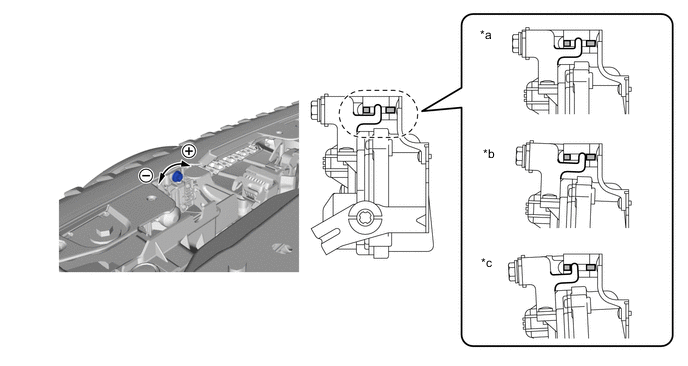
*a Standard Position *b Most Downward Position *c Most Upward Position - - Turn the bolt to change the beam axis of the millimeter wave radar sensor assembly.
Vertical axis change Upward direction: Turn screwdriver to negative (-) side Downward direction: Turn screwdriver to positive (+) side 1.5 N*m 15 kgf*cm 13 in.*lbf Note:The manual axis switching mechanism may get damaged if a torque higher than the above is applied.
If the manual axis switching mechanism is damaged, replace the No. 1 millimeter wave radar sensor bracket.
Tip:
-
Make sure to set the beam axis to the most upward or downward position.
-
Manually change the beam axis to the position *b (most downward position) when error code 12 (radar axis aiming failure upward) is displayed.
-
Manually change the beam axis to the position *c (most upward position) when error code 13 (radar axis aiming failure downward) is displayed.
-
-
Perform Front Beam Axis Adjustment. (See page 5. ADJUST MILLIMETER WAVE RADAR SENSOR ASSEMBLY VERTICALLY AND HORIZONTALLY (c) Front Beam Axis Adjustment)
-
Install the lower radiator air deflector.
-
Install the radiator cover plate.
-
Install the upper radiator support seal.
-
- Click here
INSTALL CHECK VEHICLE HEIGHT CONTROL (for 2WD)
- Click here
INSTALL CHECK VEHICLE HEIGHT CONTROL (for AWD)