LANE CONTROL SYSTEM(for Stereo Camera Type) Steering Pad Switch Circuit
DESCRIPTION
The driving support ECU assembly receives a LTA main switch signal from the steering pad switch assembly and sends the signal to the object recognition camera via CAN communication.
WIRING DIAGRAM
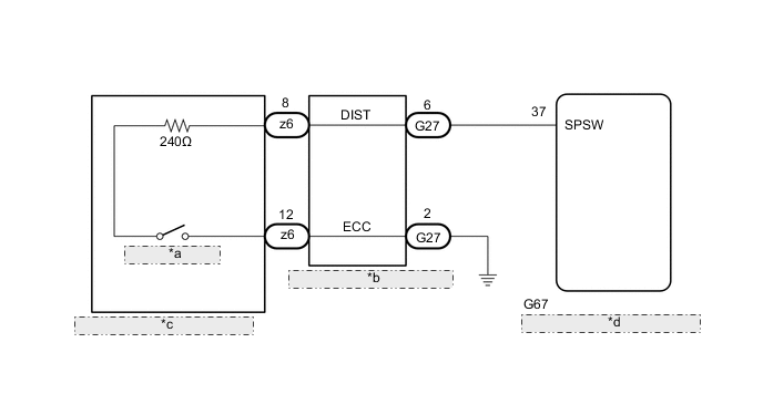
| *a | LTA main switch |
| *b | Spiral with Sensor Cable Sub-assembly |
| *c | Steering Pad Switch Assembly |
| *d | Driving Support ECU Assembly |
CAUTION / NOTICE / HINT
Note
-
When replacing the driving support ECU assembly, make sure to replace it with a new one. If a device which was installed to another vehicle is used, the information stored in the driving support ECU assembly will not match the information from the vehicle, and as a result, a DTC may be stored.
-
The vehicle is equipped with a Supplemental Restraint System (SRS) which includes components such as airbags. Before servicing (including removal or installation of parts), be sure to read the precaution for Supplemental Restraint System.
PROCEDURE
-
INSPECT STEERING PAD SWITCH ASSEMBLY
-
Remove the steering pad switch assembly.
-
Inspect the steering pad switch assembly.
Result Proceed to OK NG
NG 
REPLACE STEERING PAD SWITCH ASSEMBLY Click here
OK 
-
-
INSPECT SPIRAL WITH SENSOR CABLE SUB-ASSEMBLY
-
Remove the spiral with sensor cable sub-assembly.
-
Inspect the spiral with sensor cable sub-assembly.
Result Proceed to OK NG
NG
REPLACE SPIRAL WITH SENSOR CABLE SUB-ASSEMBLY Click here
OK
-
-
CHECK HARNESS AND CONNECTOR (SPIRAL WITH SENSOR CABLE SUB-ASSEMBLY - DRIVING SUPPORT ECU ASSEMBLY)
-
Disconnect the G27 spiral with sensor cable sub-assembly connector.
-
Disconnect the G67 driving support ECU assembly connector.
-
Measure the resistance according to the value(s) in the table below.
Standard Resistance (Check for Open) Tester Connection Condition Specified Condition G27-6 (DIST) - G67-37 (SPSW) Always Below 1 Ω Standard Resistance (Check for Short) Tester Connection Condition Specified Condition G27-6 (DIST) or G67-37 (SPSW) - Body ground Always 10 kΩ or higher -
Connect the G67 driving support ECU assembly connector.
-
Connect the G27 spiral with sensor cable sub-assembly connector.
Result Proceed to OK NG
NG
REPAIR OR REPLACE HARNESS OR CONNECTOR (SPIRAL WITH SENSOR CABLE SUB-ASSEMBLY - DRIVING SUPPORT ECU ASSEMBLY)
OK
-
-
CHECK HARNESS AND CONNECTOR (SPIRAL WITH SENSOR CABLE SUB-ASSEMBLY - BODY GROUND)
-
Disconnect the G27 spiral cable with sensor sub-assembly connector.
-
Measure the resistance according to the value(s) in the table below.
Standard Resistance (Check for Open) Tester Connection Condition Specified Condition G27-2 (ECC) - Body ground Always Below 1 Ω -
Reconnect the G27 spiral cable with sensor sub-assembly connector.
Result Proceed to OK NG
OK
REPLACE DRIVING SUPPORT ECU ASSEMBLY Click here
NG
REPAIR OR REPLACE HARNESS OR CONNECTOR (SPIRAL WITH SENSOR CABLE SUB-ASSEMBLY - BODY GROUND)
-