AIR SUSPENSION SYSTEM, Diagnostic DTC:C123A12
| DTC Code | DTC Name |
|---|---|
| C123A12 | Supply Voltage Circuit IG Voltage Malfunction |
DESCRIPTION
| DTC No. | Detection Item | DTC Detection Condition | Trouble Area | Warning Indicate | Memory |
|---|---|---|---|---|---|
| C123A12 | Supply Voltage Circuit IG Voltage Malfunction |
|
|
Does not come on | Yes |
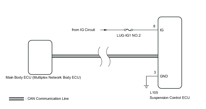
WIRING DIAGRAM
CAUTION / NOTICE / HINT
Note
-
Inspect the fuses for circuits related to this system before performing the followinginspection procedure.
-
Before performing troubleshooting, inspect the connectors of related circuits.
-
After replacing the Suspension Control ECU with a new one, perform vehicle height offset calibration.
PROCEDURE
-
READ VALUE USING GTS (IG SW Signal)
-
Turn the power switch off.
-
Connect the GTS to the DLC3.
-
Turn the power switch on (IG).
-
Turn the GTS on.
-
Enter the following menus: Chassis / Air suspension / Data List.
OK The values are as specified in the normal condition column.
Chassis > Air suspensionTester Display Measurement Item Range Normal Condition Diagnostic Note IG SW Signal IG SW signal ON or OFF ON: Power switch on (IG)
OFF: Power switch off
"OFF" is also displayed for this item when the power switch is on (ACC).
Chassis > Air suspension > Data ListTester Display IG SW Signal Result Result Proceed to OK A NG B
B 
REPAIR MAIN BODY ECU (MULTIPLEX NETWORK BODY ECU) IG CIRCUIT
A 
-
-
CHECK TERMINAL VOLTAGE (IG TERMINAL)
-
Turn the power switch off.
-
Disconnect the L105 suspension control ECU connector.
-
Measure the resistance according to the value(s) in the table below.
Standard Resistance Tester Connection Condition Specified Condition L105-8 (IG) - Body ground Power switch off Below 1 V Result Proceed to OK NG
OK
REPLACE SUSPENSION CONTROL ECU Click here
NG
REPAIR OR REPLACE HARNESS OR CONNECTOR
-