| DTC Code | DTC Name |
|---|---|
| C171114 | Front Height Control Sensor RH Circuit Circuit Short to Ground or Open |
| C171214 | Front Height Control Sensor LH Circuit Circuit Short to Ground or Open |
| C171314 | Rear Height Control Sensor RH Circuit Circuit Short to Ground or Open |
| C171414 | Rear Height Control Sensor LH Circuit Circuit Short to Ground or Open |
DESCRIPTION
The height control sensor sub-assembly changes the resistance according to the change in vehicle height. The suspension control ECU outputs a fixed voltage of 5 V to the height control sensor sub-assembly SHB terminal. If the sensor's resistance value changes, the sensor's voltage changes accordingly. The suspension control ECU then inputs the voltage value from the sensor to detect the vehicle height change.
| DTC No. | Detection Item | DTC Detection Condition | Trouble Area | Warning Indicate | Memory |
|---|---|---|---|---|---|
| C171114 | Front Height Control Sensor RH Circuit Circuit Short to Ground or Open |
|
|
Comes on | Yes |
| C171214 | Front Height Control Sensor LH Circuit Circuit Short to Ground or Open |
|
|
Comes on | Yes |
| C171314 | Rear Height Control Sensor RH Circuit Circuit Short to Ground or Open |
|
|
Comes on | Yes |
| C171414 | Rear Height Control Sensor LH Circuit Circuit Short to Ground or Open |
|
|
Comes on | Yes |
CAUTION / NOTICE / HINT
-
Before performing troubleshooting, inspect the connectors of related circuits.
-
After replacing the suspension control ECU or height control sensor sub-assembly with a new one, perform vehicle height offset.
PROCEDURE
- Click here
CHECK FOR DTCS (ADAPTIVE VARIABLE SUSPENSION SYSTEM)
-
Check for DTCs.
- Chassis > Adaptive Variable Suspension System > Trouble Codes
-
-
Tip:If there is a malfunction in the height control sensor, adaptive variable suspension system DTCs may be detected. Check the adaptive variable suspension system first.
Result Result Proceed to Adaptive variable suspension system DTCs are not output A Adaptive variable suspension system DTCs are output B
- AClick here
- B
GO TO ADAPTIVE VARIABLE SUSPENSION SYSTEM (HOW TO PROCEED WITH TROUBLESHOOTING)Click here
-
- Click here
CHECK HEIGHT CONTROL SENSOR SUB-ASSEMBLY INSTALLATION CONDITION
-
Check the height control sensor sub-assembly installation condition and make sure that there are no loose installation bolts and foreign matter trapped between the sensor and body.
OK Installed correctly. Result Proceed to OK NG
- OKClick here
- NG
INSTALL HEIGHT CONTROL SENSOR SUB-ASSEMBLY CORRECTLY for Front Side :Click here
INSTALL HEIGHT CONTROL SENSOR SUB-ASSEMBLY CORRECTLY for Rear Side :Click here
-
- Click here
INSPECT HEIGHT CONTROL SENSOR SUB-ASSEMBLY (FRONT OR REAR)
-
For Front Side.
-
Turn the power switch off.
-
Inspect the front height control sensor sub-assembly RH or front height control sensor sub-assembly LH.
-
-
For Rear Side.
-
Turn the power switch off.
-
Inspect the rear height control sensor sub-assembly RH or rear height control sensor sub-assembly LH.
Result Result Proceed to OK (for Front Side) A OK (for Rear Side) B Front height control sensor sub-assembly RH malfunction C Front height control sensor sub-assembly LH malfunction D Rear height control sensor sub-assembly RH malfunction E Rear height control sensor sub-assembly LH malfunction F -
- AClick here
- BClick here
- C
REPLACE FRONT HEIGHT CONTROL SENSOR SUB-ASSEMBLY RHClick here
- D
REPLACE FRONT HEIGHT CONTROL SENSOR SUB-ASSEMBLY LHClick here
- E
REPLACE REAR HEIGHT CONTROL SENSOR SUB-ASSEMBLY RHClick here
- F
REPLACE REAR HEIGHT CONTROL SENSOR SUB-ASSEMBLY LHClick here
-
- Click here
CHECK HARNESS AND CONNECTOR (FRONT HEIGHT CONTROL SENSOR SUB-ASSEMBLY - SUSPENSION CONTROL ECU)
-
Check the front height control sensor sub-assembly RH harness and connector.
-
Turn the power switch off.
-
Disconnect the A69*1 or A75*2 front height control sensor sub-assembly RH connector.
-
*1: for AWD
-
*2: for 2WD
-
-
Disconnect the L105 suspension control ECU connector.
-
Measure the resistance according to the value(s) in the table below.
Standard Resistance Table 1. for AWD Tester Connection Condition Specified Condition A69-2 (SHFR) - L105-13 (SHFR) Always Below 1 Ω A69-2 (SHFR) or L105-13 (SHFR) - Body ground Always 10 kΩ or higher A69-3 (SHB) - L105-25 (SHB1) Always Below 1 Ω A69-3 (SHB) or L105-25 (SHB1) - Body ground Always 10 kΩ or higher Table 2. for 2WD Tester Connection Condition Specified Condition A75-2 (SHFR) - L105-13 (SHFR) Always Below 1 Ω A75-2 (SHFR) or L105-13 (SHFR) - Body ground Always 10 kΩ or higher A75-3 (SHB) - L105-25 (SHB1) Always Below 1 Ω A75-3 (SHB) or L105-25 (SHB1) - Body ground Always 10 kΩ or higher
-
-
Check the front height control sensor sub-assembly LH harness and connector.
-
Turn the power switch off.
-
Disconnect the A68*1 or A74*2 front height control sensor sub-assembly LH connector.
-
*1: for AWD
-
*2: for 2WD
-
-
Disconnect the L105 suspension control ECU connector.
-
Measure the resistance according to the value(s) in the table below.
Standard Resistance Table 3. for AWD Tester Connection Condition Specified Condition A68-2 (SHFL) - L105-23 (SHFL) Always Below 1 Ω A68-2 (SHFL) or L105-23 (SHFL) - Body ground Always 10 kΩ or higher A68-3 (SHB) - L105-11 (SHB2) Always Below 1 Ω A68-3 (SHB) or L105-11 (SHB2) - Body ground Always 10 kΩ or higher Table 4. for 2WD Tester Connection Condition Specified Condition A75-2 (SHFL) - L105-23 (SHFL) Always Below 1 Ω A75-2 (SHFL) or L105-23 (SHFL) - Body ground Always 10 kΩ or higher A75-3 (SHB) - L105-11 (SHB2) Always Below 1 Ω A75-3 (SHB) or L105-11 (SHB2) - Body ground Always 10 kΩ or higher
Result Result OK NG -
- OK
REPLACE SUSPENSION CONTROL ECUClick here
- NG
REPAIR OR REPLACE HARNESS AND CONNECTOR
-
- Click here
CHECK HARNESS AND CONNECTOR (REAR HEIGHT CONTROL SENSOR SUB-ASSEMBLY - SUSPENSION CONTROL ECU)
-
Turn the power switch off.
-
Disconnect the L104 suspension control ECU connector.
-
Disconnect the z26 or L179 skid control sensor wire connector.
-
Measure the resistance according to the value(s) in the table below.
Standard Resistance Table 5. RH Tester Connection Condition Specified Condition L104-23 (SHRR) - z26-2 (SHRR) Always Below 1 Ω L104-23 (SHRR) or z26-2 (SHRR) - Body ground Always 10 kΩ or higher L104-24 (SHB3) - z26-3 (SHB) Always Below 1 Ω L104-24 (SHB3) or z26-3 (SHB) - Body ground Always 10 kΩ or higher Table 6. LH Tester Connection Condition Specified Condition L104-26 (SHRL) - L179-2 (SHRL) Always Below 1 Ω L104-26 (SHRL) or L179-2 (SHRL) - Body ground Always 10 kΩ or higher L104-27 (SHB4) - L179-3 (SHB) Always Below 1 Ω L104-27 (SHB4) or L179-3 (SHB) - Body ground Always 10 kΩ or higher Result Result OK NG
- OK
REPLACE SUSPENSION CONTROL ECUClick here
- NGClick here
-
- Click here
INSPECT SKID CONTROL SENSOR WIRE
-
Turn the power switch off.
-
Disconnect the L175 or A skid control sensor wire connector.
-
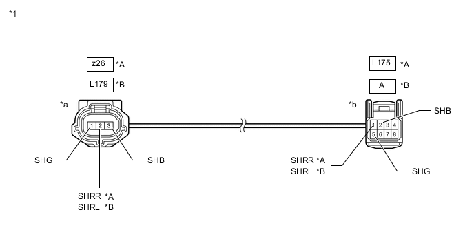
*A RH *B LH *1 Skid Control Sensor Wire - - *a Front view of wire harness connector
(to Rear Height Control Sensor Sub-assembly Side Connector)
*b Front view of wire harness connector
(to Vehicle Side Connector)
Measure the resistance according to the value(s) in the table below.
Standard Resistance Table 7. for RH Tester Connection Condition Specified Condition L175 -1 (SHRR) - z26 -2 (SHRR) Always Below 1 Ω L175 -1 (SHRR) or z26 -2 (SHRR) - Body ground Always 10 kΩ or higher L175 -2 (SHB) - z26 -3 (SHB) Always Below 1 Ω L175 -2 (SHB) or z26 -3 (SHB) - Body ground Always 10 kΩ or higher Table 8. for LH Tester Connection Condition Specified Condition A -1 (SHRL) - L179 -2 (SHRL) Always Below 1 Ω A -1 (SHRL) or L179 -2 (SHRL) - Body ground Always 10 kΩ or higher A -2 (SHB) - L179 -3 (SHB) Always Below 1 Ω A -2 (SHB) or L179 -3 (SHB) - Body ground Always 10 kΩ or higher Result Proceed to OK NG
- OK
REPAIR OR REPLACE HARNESS AND CONNECTOR
- NG
REPLACE SKID CONTROL SENSOR WIREClick here
-