FRONT DISC BRAKE PAD(except 6-Pot Caliper) INSTALLATION

CAUTION / NOTICE / HINT
Tech Tips
-
Use the same procedure for the RH and LH sides, except where indicated.
-
The following procedure is for the LH side.
PROCEDURE
-
INSTALL FRONT DISC BRAKE ANTI-SQUEAL SHIM
-
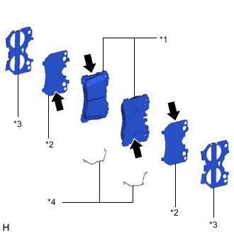
*1 Front Disc Brake Pad *2 No. 1 Anti-Squeal Shim *3 No. 2 Anti-Squeal Shim *4 Inner Anti-Rattle Spring 
Disc Brake Grease Apply disc brake grease to the front disc brake pads and No. 1 anti-squeal shims at the positions shown in the illustration.
Note
-
Use the grease supplied with the anti-squeal shim kit or disc brake grease as the disc brake grease.
-
Keep the lining surface of the front disc brake pad free from grease.
-
Do not apply grease between the No. 1 and No. 2 anti-squeal shims.
-
-
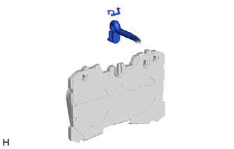
Install the inner anti-rattle springs to each of the front disc brake pads.
-
Install the No. 1 and No. 2 anti-squeal shims to each of the front disc brake pads.
-
-
INSTALL FRONT DISC BRAKE PAD
CAUTION:
Be careful not to get pinched by the disc brake cylinder assembly LH or other parts when installing the front disc brake pads.
-
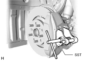
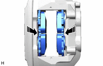
Using SST, push back the front disc brake pistons.
- SST
- 09719-77020
Note
-
Make sure the brake fluid does not overflow from the reservoir.
-
Do not forcibly push in the front disc brake pistons.
-
for RH side:
-
Install the pad wear indicator wire assembly RH to the front disc brake pad (inner) with a new pad wear indicator clip.
Note
-
The front disc brake pad with the pad wear indicator wire assembly RH must be installed to the inside position.
-
When replacing the front disc brake pads with new ones, make sure to replace the pad wear indicator wire assembly RH and pad wear indicator clip at the same time.
-
-
-
Install the 2 front disc brake pads to the disc brake cylinder assembly LH.
-
Install the anti-squeal spring between the 2 front disc brake pads.
-
Install the No. 1 anti-rattle spring to the disc brake cylinder LH.
-
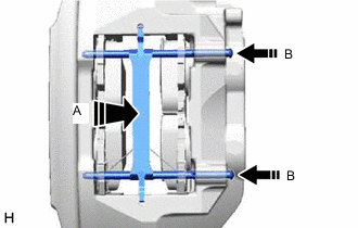
While pressing the area (A), install the 2 hole pins (B).
-
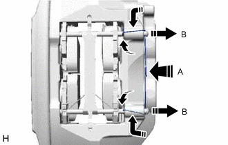
While pressing the area (A), slightly pull out the hole pin (B) from the disc brake cylinder assembly LH, and install the pin hold clip.
-
for RH side:
-
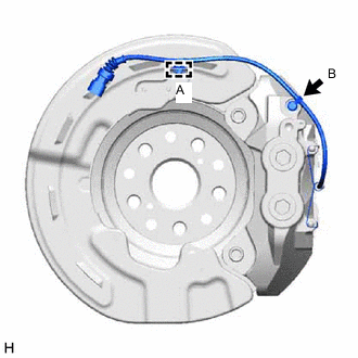
Attach the pad wear indicator wire assembly RH to the front disk brake dust cover RH with the clamp (A).
-
Connect the bleeder plug cap (B) to the disk brake cylinder RH.
-
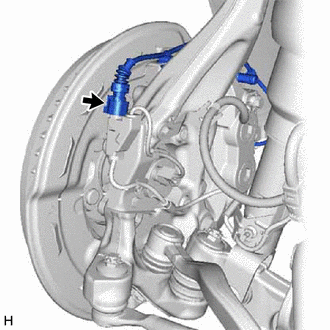
Connect the pad wear indicator wire assembly RH connector to the front skid control sensor wire.
-
-
-
CONNECT BRAKE BOOSTER PUMP CONNECTOR
-
INSPECT BRAKE FLUID LEVEL IN RESERVOIR
-
INSTALL FRONT WHEEL