ACTIVE REAR WING ECU REMOVAL
CAUTION / NOTICE / HINT
The necessary procedures (adjustment, calibration, initialization, or registration) that must be performed after parts are removed, installed, or replaced during the active rear wing ECU removal/installation are shown below.
| Replacement Part or Procedure | Necessary Procedure | Effect/Inoperative when not Performed | Link |
|---|---|---|---|
| Disconnect cable from negative auxiliary battery terminal | Memorize steering angle neutral point | LKA/LDA system | |
| Pre-collision system | |||
| Parking assist monitor system | |||
| Steering sensor zero point calibration | Variable gear ratio steering system | ||
| Spoiler control ECU assembly | Initialization | Active rear wing system |
PROCEDURE
-
PRECAUTION
Note
After turning the power switch off, waiting time may be required before disconnecting the cable from the negative (-) auxiliary battery terminal. Therefore, make sure to read the disconnecting the cable from the negative (-) auxiliary battery terminal notices before proceeding with work.
-
REMOVE NO. 2 DECK BOARD
-
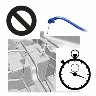
DISCONNECT CABLE FROM NEGATIVE AUXILIARY BATTERY TERMINAL
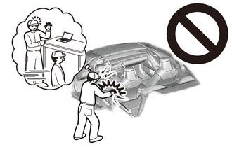
CAUTION:
-
Wait at least 90 seconds after disconnecting the cable from the negative(-) auxiliary battery terminal to disable the SRS system.
-
If the airbag deploys for any reason, it may cause a serious accident.
Note
When disconnecting the cable, some systems need to be initialized after the cable is reconnected.
-
-
REMOVE NO. 1 DECK BOARD
-
REMOVE LUGGAGE COMPARTMENT TRIM COVER LH
-
REMOVE REAR FLOOR FINISH PLATE
-
REMOVE FRONT LUGGAGE COMPARTMENT TRIM COVER
-
REMOVE INNER LUGGAGE COMPARTMENT TRIM COVER LH
-
REMOVE NO. 3 DECK BOARD BRACKET
-
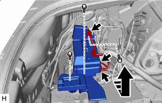

Remove in this Direction Disconnect the 3 connectors.
-
Remove the 3 bolts and No. 3 deck board bracket as shown in the illustration.
-
-
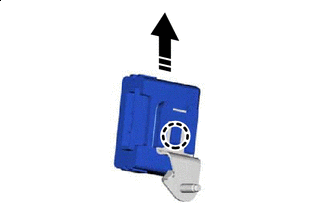
REMOVE SPOILER CONTROL ECU ASSEMBLY
-
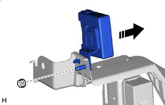
Remove in this Direction Remove the nut and spoiler control ECU assembly from the No. 3 deck board bracket as shown in the illustration.
-
-
REMOVE NO. 1 COMPUTER BRACKET
-
Remove in this Direction Detach the claw and remove the spoiler control ECU assembly as shown in the illustration.
-