ACTIVE REAR WING SYSTEM Both Manual and Automatic Operation of Active Rear Wing does not Operate
DESCRIPTION
When the active rear wing cannot be operated by either manual or automatic operation, there may be a malfunction in the spoiler control ECU assembly power supply, ground circuit, spoiler control ECU assembly or rear spoiler motor assembly may be malfunctioning.
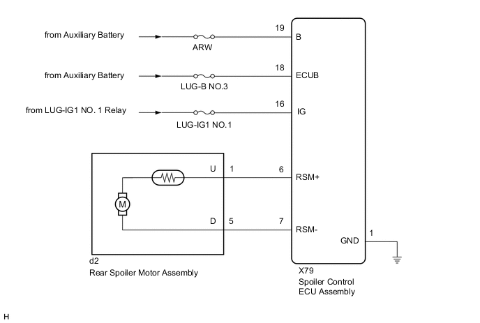
WIRING DIAGRAM
CAUTION / NOTICE / HINT
Note
Inspect the fuses for circuits related to this system before performing the following procedure.
PROCEDURE
-
READ VALUE USING GTS
-
Connect the GTS to the DLC3.
-
Turn the power switch on (IG).
-
Turn the GTS on.
-
Enter the following menus: Customize Setting / Others.
-
Check that the active rear wing system customize setting "Active Rear Wing Control" is set to "Permission".
OthersTester Display Description Default Setting ECU Active Rear Wing Control Active rear wing system permission/prohibition setting Prohibition 01:Permission,10:Prohibition Spoiler control ECU assembly OK The active rear wing system customize setting "Active Rear Wing Control" is set to "Permission". Result Proceed to OK NG
NG 
PERFORM CUSTOMIZE FUNCTION (Change setting to "Permission") Click here
OK 
-
-
CHECK FOR DTC
-
Check for DTCs.
Body Electrical > Active Rear Wing > Trouble CodesOK DTCs are not output. Result Proceed to OK NG
NG
GO TO DIAGNOSTIC TROUBLE CODE CHART Click here
OK
-
-
READ VALUE USING GTS
-
Connect the GTS to the DLC3.
-
Turn the power switch on (IG).
-
Turn the GTS on.
-
Enter the following menus: Body Electrical / Active Rear Wing / Data List.
-
Read the Data List according to the display on the GTS.
Body Electrical > Active Rear Wing > Data ListTester Display Measurement Item Range Normal Condition Diagnostic Note Vehicle Speed Information Vehicle speed signal reception condition OK or NG OK: Vehicle speed signal is valid
NG: Vehicle speed signal is invalid
-
Body Electrical > Active Rear Wing > Data ListTester Display Vehicle Speed Information Result Result Proceed to OK is displayed on the GTS A NG is displayed on the GTS B
B
GO TO ELECTRONICALLY CONTROLLED BRAKE SYSTEM Click here
A
-
-
CHECK HARNESS AND CONNECTOR (SPOILER CONTROL ECU ASSEMBLY BODY GROUND)
-
Disconnect the X79 spoiler control ECU assembly connector.
-
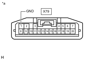
*a Front view of wire harness connector
(to Spoiler Control ECU Assembly)
Measure the resistance according to the value(s) in the table below.
Standard Resistance Tester Connection Condition Specified Condition X79-1 (GND) - Body ground Always Below 1 Ω Result Proceed to OK NG
NG
REPAIR OR REPLACE HARNESS OR CONNECTOR
OK
-
-
CHECK HARNESS AND CONNECTOR (SPOILER CONTROL ECU ASSEMBLY POWER SOURCE)
-
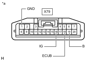
*a Front view of wire harness connector
(to Spoiler Control ECU Assembly)
Disconnect the X79 spoiler control ECU assembly connector.
-
Measure the voltage according to the value(s) in the table below.
Standard Voltage Tester Connection Switch Condition Specified Condition X79-18 (ECUB) - X79-1 (GND) Power switch off 11 to 14 V X79-19 (B) - X79-1 (GND) Power switch off 11 to 14 V X79-16 (IG) - X79-1 (GND) Power switch off Below 1 V X79-16 (IG) - X79-1 (GND) Power switch on (IG) 11 to 14 V Result Proceed to OK NG
NG
REPAIR OR REPLACE HARNESS OR CONNECTOR
OK
-
-
INSPECT REAR SPOILER MOTOR ASSEMBLY
-
Remove the rear spoiler motor assembly.
-
Inspect the rear spoiler motor assembly.
Result Proceed to OK NG
NG
REPLACE REAR SPOILER MOTOR ASSEMBLY Click here
OK
-
-
CHECK HARNESS AND CONNECTOR (SPOILER CONTROL ECU ASSEMBLY - REAR SPOILER MOTOR ASSEMBLY)
-
Measure the resistance according to the value(s) in the table below.
Standard Resistance Tester Connection Condition Specified Condition X79-6 (RSM+) - d2-1 (U) Always Below 1 Ω X79-6 (RSM+) or d2-1 (U) - Body ground Always 10 kΩ or higher X79-7 (RSM-) - d2-5 (D) Always Below 1 Ω X79-7 (RSM-) or d2-5 (D) - Body ground Always 10 kΩ or higher Result Proceed to OK NG
OK
REPLACE SPOILER CONTROL ECU ASSEMBLY Click here
NG
REPAIR OR REPLACE HARNESS OR CONNECTOR
-