ACTIVE REAR WING SYSTEM, Diagnostic DTC:B1318
| DTC Code | DTC Name |
|---|---|
| B1318 | Short in Manual Switch Circuit |
DESCRIPTION
This DTC is stored when the No. 4 combination switch assembly (spoiler control switch) is determined to be stuck on or there is a short in the No. 4 combination switch assembly (spoiler control switch) circuit.
| DTC No. | Detection Item | DTC Detection Condition | Trouble Area |
|---|---|---|---|
| B1318 | Short in Manual Switch Circuit | When voltage at terminal ECUB of the spoiler control ECU assembly is 9 V or more, the No. 4 combination switch assembly (spoiler control switch) is stuck on for 30 seconds or more. |
|
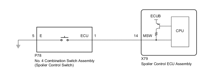
WIRING DIAGRAM
PROCEDURE
-
READ VALUE USING GTS
-
Connect the GTS to the DLC3.
-
Turn the power switch on (IG).
-
Turn the GTS on.
-
Enter the following menus: Body Electrical / Active Rear Wing / Data List.
-
Read the Data List according to the display on the GTS.
Body Electrical > Active Rear Wing > Data ListTester Display Measurement Item Range Normal Condition Diagnostic Note Manual Switch No. 4 combination switch assembly (Spoiler control switch) condition OFF or ON OFF: No. 4 combination switch assembly (Spoiler control switch) not pressed
ON: No. 4 combination switch assembly (Spoiler control switch) pressed
-
Body Electrical > Active Rear Wing > Data ListTester Display Manual Switch OK The GTS display changes according to the No. 4 combination switch assembly (spoiler control switch). Result Proceed to OK NG
OK 
REPLACE SPOILER CONTROL ECU ASSEMBLY Click here
NG 
-
-
INSPECT NO. 4 COMBINATION SWITCH ASSEMBLY (SPOILER CONTROL SWITCH)
-
Remove the No. 4 combination switch assembly (spoiler control switch).
-
Inspect the No. 4 combination switch assembly (spoiler control switch).
Result Result OK NG
NG
REPLACE NO. 4 COMBINATION SWITCH ASSEMBLY (SPOILER CONTROL SWITCH) Click here
OK
-
-
CHECK HARNESS AND CONNECTOR (SPOILER CONTROL ECU ASSEMBLY - NO. 4 COMBINATION SWITCH ASSEMBLY [SPOILER CONTROL SWITCH])
-
Disconnect the X79 spoiler control ECU assembly connector.
-
Measure the resistance according to the value(s) in the table below.
Standard Resistance Tester Connection Condition Specified Condition X79-14 (MSW) or P78-1(ECU) - Body ground Always 10 kΩ or higher Result Result OK NG
OK
REPLACE SPOILER CONTROL ECU ASSEMBLY Click here
NG
REPAIR OR REPLACE HARNESS OR CONNECTOR
-