ACTIVE REAR WING SYSTEM, Diagnostic DTC:B131A, B131E
| DTC Code | DTC Name |
|---|---|
| B131A | Position Initialization Incomplete |
| B131E | Motor Circuit |
DESCRIPTION
DTC B131A is stored when initialization does not complete normally when using the GTS or No. 4 combination switch assembly (spoiler control switch).
DTC B131E is stored when the rear spoiler motor assembly is operated continuously for a certain amount of time.
| DTC No. | Detection Item | DTC Detection Condition | Trouble Area |
|---|---|---|---|
| B131A | Position Initialization Incomplete | Initialization using the GTS or No. 4 combination switch assembly (spoiler control switch) does not complete within 10 seconds. |
|
| B131E | Motor Circuit | The rear spoiler motor assembly is operated continuously for 20 seconds or more. |
|
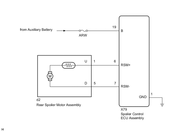
WIRING DIAGRAM
CAUTION / NOTICE / HINT
Note
Inspect the fuses for circuits related to this system before performing the following procedure.
PROCEDURE
-
CHECK FOR FOREIGN OBJECT
-
Check that no foreign objects are restricting active rear wing operation.
OK No foreign objects. Result Proceed to OK NG
NG 
REMOVE FOREIGN OBJECT
OK 
-
-
CHECK HARNESS AND CONNECTOR (SPOILER CONTROL ECU ASSEMBLY POWER SOURCE)
-
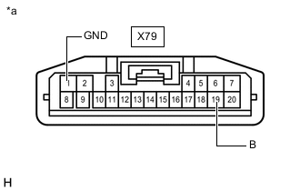
*a Front view of wire harness connector
(to Spoiler Control ECU Assembly)
Disconnect the X79 spoiler control ECU assembly connector.
-
Measure the voltage according to the value(s) in the table below.
Standard Voltage Tester Connection Switch Condition Specified Condition X79-19 (B) - X79-1 (GND) Power switch off 11 to 14 V Result Result OK NG
NG
REPAIR OR REPLACE HARNESS OR CONNECTOR
OK
-
-
CHECK HARNESS AND CONNECTOR (SPOILER CONTROL ECU ASSEMBLY - REAR SPOILER MOTOR ASSEMBLY)
-
Disconnect the d2 rear spoiler motor assembly connector.
-
Measure the resistance according to the value(s) in the table below.
Standard Resistance Tester Connection Condition Specified Condition X79-6 (RSM+) - d2-1 (U) Always Below 1 Ω X79-6 (RSM+) or d2-1 (U) - Body ground Always 10 kΩ or higher X79-7 (RSM-) - d2-5 (D) Always Below 1 Ω X79-7 (RSM-) or d2-5 (D) - Body ground Always 10 kΩ or higher Result Proceed to OK NG
NG
REPAIR OR REPLACE HARNESS OR CONNECTOR
OK
-
-
INSPECT ACTIVE REAR WING ASSEMBLY
-
Remove the active rear wing assembly.
-
Visually check the top cover lock control link sub-assembly LH, top cover lock control link sub-assembly RH and rear spoiler drive gear for damage or deformation.
Tech Tips
To visually check the top cover lock control link sub-assembly LH and top cover lock control link sub-assembly RH, it is necessary to remove the rear spoiler cover LH and rear spoiler cover RH.
Result Result Proceed to No damage or deformation A Top cover lock control link sub-assembly LH is damaged or deformed B Top cover lock control link sub-assembly RH is damaged or deformed C Rear spoiler drive gear is damaged or deformed D
B
REPLACE TOP COVER LOCK CONTROL LINK SUB-ASSEMBLY LH Click here
C
REPLACE TOP COVER LOCK CONTROL LINK SUB-ASSEMBLY RH Click here
D
REPLACE REAR SPOILER DRIVE GEAR Click here
A
-
-
INSPECT REAR SPOILER MOTOR ASSEMBLY
-
Remove the rear spoiler motor assembly.
-
Inspect the rear spoiler motor assembly.
Result Proceed to OK NG
OK
REPLACE SPOILER CONTROL ECU ASSEMBLY Click here
NG
REPLACE REAR SPOILER MOTOR ASSEMBLY Click here
-