ACTIVE REAR WING SYSTEM, Diagnostic DTC:B1311
| DTC Code | DTC Name |
|---|---|
| B1311 | Hall IC Pulse Sensor Main or Sub |
DESCRIPTION
This DTC is stored when a malfunction of either Hall IC (Hall IC1 or Hall IC2) is detected.
| DTC No. | Detection Item | DTC Detection Condition | Trouble Area |
|---|---|---|---|
| B1311 | Hall IC Pulse Sensor Main or Sub | When the rear spoiler motor assembly is operating, a pulse signal of 20 edges or more is received from either Hall IC (Hall IC1 or Hall IC2) but a pulse signal is not received from the other Hall IC. |
|
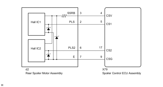
WIRING DIAGRAM
CAUTION / NOTICE / HINT
CAUTION:
Be careful not to get pinched by the active rear wing assembly when the active rear wing is operating.
PROCEDURE
-
CHECK FOR FOREIGN OBJECT
-
Check that no foreign objects are restricting active rear wing operation.
OK No foreign objects. Result Proceed to OK NG
NG 
REMOVE FOREIGN OBJECT
OK 
-
-
CHECK CONNECTOR CONNECTION
-
Check that the connectors are properly connected to the spoiler control ECU assembly and rear spoiler motor assembly.
OK Connectors are properly connected. Result Proceed to OK NG
NG
CONNECT CONNECTORS PROPERLY
OK
-
-
CLEAR DTC
-
Clear the DTCs.
Body Electrical > Active Rear Wing > Clear DTCsResult Proceed to NEXT
NEXT
-
-
CHECK FOR DTC
-
Raise and retract the active rear wing by manual operation.
-
Check for DTCs.
Body Electrical > Active Rear Wing > Trouble CodesOK DTC B1311 is not output. Result Proceed to OK NG
OK
USE SIMULATION METHOD TO CHECK Click here
NG
-
-
CHECK REAR SPOILER MOTOR ASSEMBLY
-
Connect the GTS to the DLC3.
-
Turn the power switch on (IG).
-
Turn the GTS on.
-
Enter the following menus: Body Electrical / Active Rear Wing / Active Test.
-
Perform the Active Test to raise or retract the active rear wing.
Note
-
Before performing the Active Test, check that "Init" is displayed for the Data List item "Initialization Status". If "Init" is not displayed, initialize the active rear wing system.
-
While performing the Active Test, if the active rear wing is stopped during an operation, it is necessary to perform initialization.
Body Electrical > Active Rear Wing > Active TestTester Display Measurement Item Control Range Diagnostic Note Wing Extend Active rear wing rise operation OFF/ON - Wing Fold Active rear wing retract operation OFF/ON -
Body Electrical > Active Rear Wing > Active TestTester Display Wing Extend
Body Electrical > Active Rear Wing > Active TestTester Display Wing Fold -
-
Measure the pulse according to the value(s) in the table below.
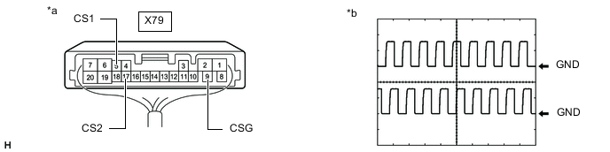
*a Component with harness connected
(Spoiler Control ECU Assembly)
*b Waveform 1 Tester Connection Condition Tool Setting Specified Condition X79-5 (CS1) - X79-9 (CSG) Active rear wing rise or retract operation being performed 5 V/DIV., 20 ms./DIV. Pulse generation
(Waveform 1)
(Below 1 V ←→ 9.5 to 13.33 V)
X79-17 (CS2) - X79-9 (CSG) Active rear wing rise or retract operation being performed 5 V/DIV., 20 ms./DIV. Pulse generation
(Waveform 1)
(Below 1 V ←→ 9.5 to 13.33 V)
Note
The waveform shown in the illustration is an example for reference only. Noise, chattering, etc. are not shown.
Result Proceed to OK NG
OK
REPLACE SPOILER CONTROL ECU ASSEMBLY Click here
NG
-
-
CHECK HARNESS AND CONNECTOR (SPOILER CONTROL ECU ASSEMBLY - REAR SPOILER MOTOR ASSEMBLY)
-
Disconnect the X79 spoiler control ECU assembly connector.
-
Disconnect the d2 rear spoiler motor assembly connector.
-
Measure the resistance according to the value(s) in the table below.
Standard Resistance Tester Connection Condition Specified Condition X79-5 (CS1) - d2-2 (PLS) Always Below 1 Ω X79-5 (CS1) or d2-2 (PLS) - Body ground Always 10 kΩ or higher X79-17 (CS2) - d2-6 (PLS2) Always Below 1 Ω X79-17 (CS2) or d2-6 (PLS2) - Body ground Always 10 kΩ or higher Result Proceed to OK NG
NG
REPAIR OR REPLACE HARNESS OR CONNECTOR
OK
-
-
CHECK SPOILER CONTROL ECU ASSEMBLY
-
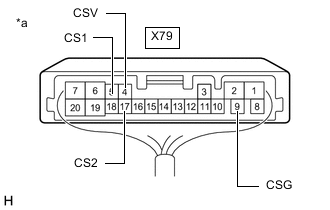
*a Component with harness connected
(Spoiler Control ECU Assembly)
Disconnect the d2 rear spoiler motor assembly connector.
-
Measure the voltage according to the value(s) in the table below.
Standard Voltage Tester Connection Switch Condition Specified Condition X79-4 (CSV) - X79-5 (CS1) Power switch on (IG) 11 to 14 V X79-9 (CSG) - X79-17 (CS2) Power switch on (IG) 11 to 14 V Result Proceed to OK NG
OK
REPLACE REAR SPOILER MOTOR ASSEMBLY Click here
NG
REPLACE SPOILER CONTROL ECU ASSEMBLY Click here
-