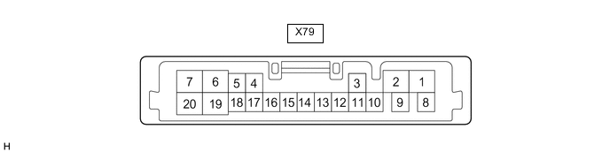
ACTIVE REAR WING SYSTEM TERMINALS OF ECU
-
SPOILER CONTROL ECU ASSEMBLY
-
Disconnect the X79 spoiler control ECU assembly.
-
Measure the voltage and resistance, and check the pulses according to the value(s) in the table below.
Tech Tips
Measure the values on the wire harness side with the connectors disconnected.
Tester Connection Wiring Color Terminal Description Condition Specified Condition X79-18 (ECUB) - Body ground LA-GR - Body ground Auxiliary battery power supply Power switch off 11 to 14 V X79-19 (B) - Body ground LA-P - Body ground Auxiliary battery power supply Power switch off 11 to 14 V X79-16 (IG) - Body ground LA-B - Body ground Ignition switch power supply Power switch off Below 1 V Power switch on (IG) 11 to 14 V X79-1 (GND) - Body ground LA - Body ground Ground Always Below 1 Ω X79-14 (MSW) - Body ground B - Body ground No. 4 combination switch assembly (Spoiler control switch) signal No. 4 combination switch assembly (Spoiler control switch) not pressed 10 kΩ or higher No. 4 combination switch assembly (Spoiler control switch) pressed Below 1 Ω -
Reconnect the X79 spoiler control ECU assembly.
-
Measure the voltage and check the pulses according to the value(s) in the table below.
Tester Connection Wiring Color Terminal Description Condition Specified Condition X79-6 (RSM+) - Body ground LA-B - Body ground Rear spoiler motor assembly operation signal Active rear wing rise operation being performed 11 to 14 V Active rear wing retract operation being performed Below 1 V X79-7 (RSM-) - Body ground LA-R - Body ground Rear spoiler motor assembly operation signal Active rear wing rise operation being performed Below 1 V Active rear wing retract operation being performed 11 to 14 V X79-4 (CSV) - Body ground BE - Body ground Hall IC power supply Power switch on (IG) 11 to 14 V X79-5 (CS1) - Body ground L - Body ground Hall IC1 signal Rear spoiler motor assembly operating Pulse generation
(Waveform 1)
(Below 1 V ←→ 9.5 to 13.33 V)
X79-17 (CS2) - Body ground V - Body ground Hall IC2 signal Rear spoiler motor assembly operating Pulse generation
(Waveform 1)
(Below 1 V ←→ 9.5 to 13.33 V)
X79-9 (CSG) - Body ground W - Body ground Hall IC ground Always Below 1 V X79-20 (IND) - Body ground P - Body ground Indicator light output Indicator light not illuminated
(Active rear wing fully retracted)
11 to 14 V Indicator light illuminated
(Active rear wing raised)
Below 1 V -
Using an oscilloscope, check the waveform.
Note
The waveform shown in the illustration is an example for reference only. Noise, chattering, etc. are not shown.
-
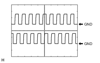
Waveform 1 (Reference)
Item Content Tester Connection
-
X79-5 (CS1) - Body ground
-
X79-17 (CS2) - Body ground
Tool Setting 5 V/DIV., 20 ms./DIV. Condition Rear spoiler motor assembly operating -
-
-