FRONT BUMPER REASSEMBLY
PROCEDURE
-
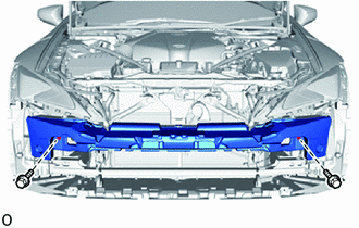
INSTALL FRONT BUMPER REINFORCEMENT SUB-ASSEMBLY
-
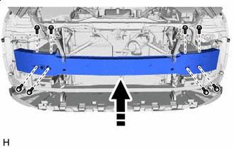

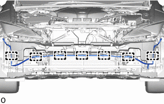
Install in this Direction Install the front bumper reinforcement sub-assembly with the 8 bolts.
- Torque:
- 38 N*m { 387 kgf*cm, 28 ft.*lbf }
-
-
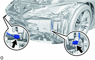
INSTALL LOWER ARM BRACKET BRACE SUB-ASSEMBLY LH
-
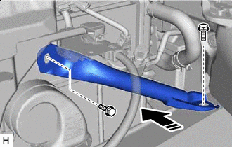
Install in this Direction Install the lower arm bracket brace sub-assembly LH with the 2 bolts.
- Torque:
- 20 N*m { 204 kgf*cm, 15 ft.*lbf }
-
-
INSTALL LOWER ARM BRACKET BRACE SUB-ASSEMBLY RH
Tech Tips
Use the same procedure described for the LH side.
-
INSTALL HEADLIGHT ASSEMBLY LH
-
INSTALL HEADLIGHT ASSEMBLY RH
Tech Tips
Use the same procedure described for the LH side.
-
INSTALL FRONT BUMPER ENERGY ABSORBER
-
INSTALL PEDESTRIAN DETECTION CHAMBER ASSEMBLY
-
INSTALL NO. 2 FRONT BUMPER MOUNTING BRACKET
-
Check that the power switch off.
-
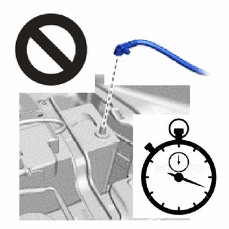
Check that the cable is disconnected from the negative (-) auxiliary battery terminal.
CAUTION:
Wait at least 90 seconds after disconnecting the cable from the negative (-) auxiliary battery terminal to disable the SRS system.
-
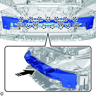
Install in this Direction Attach the guides and claws.
-
Install the No. 2 front bumper mounting bracket with the 2 bolts.
- Torque:
- 7.5 N*m { 76 kgf*cm, 66 in.*lbf }
-
Connect the 2 connectors of the pedestrian detection chamber assembly.
Note
When connecting any pedestrian detection chamber assembly connector, take care not to damage the pedestrian detection chamber assembly wire harness.
-
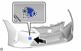
Before connecting the connector, check that the position of the housing lock is correct as shown in the illustration.
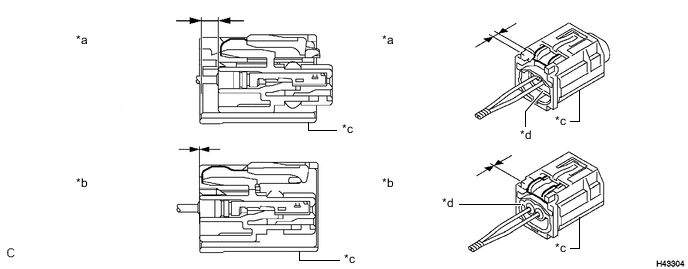
*a Correct *b Incorrect *c CPA *d Housing -
While holding the CPA be sure to engage the connectors until they are locked and check that the CPA is in its original position (when locking, make sure that a click sound can be heard).
Tech Tips
When engaged, the white housing lock will slide. Be sure not to hold the white housing lock and upper part of the CPA, as it may result in an insecure fit.
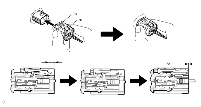
*a CPA Upper Part *b Housing Lock *c CPA *d Connection is Completed
-
-
-
CONNECT CABLE TO NEGATIVE AUXILIARY BATTERY TERMINAL
-
INSTALL NO. 2 DECK BOARD
-
INSTALL HEADLIGHT CLEANER HOSE
-
Attach the clamps and install the headlight cleaner hose.
-
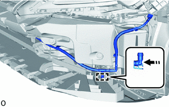
Install in this Direction Connect the headlight cleaner hose as shown in the illustration.
-
-
INSTALL LOWER RADIATOR GRILLE
-
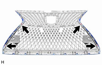
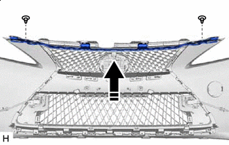
INSTALL UPPER RADIATOR GRILLE
Install in this Direction
-
Attach the claws.
-
Install the upper radiator grille with the 2 screws.
-
-
INSTALL NO. 2 RADIATOR GRILLE MOULDING
-
Install in this Direction Attach the claws.
-
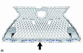
Install the No. 2 radiator grille moulding with the screw.
-
-
INSTALL RADIATOR GRILLE MOULDING
-
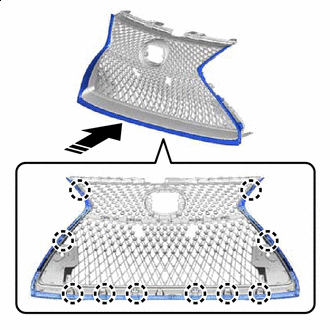
Install in this Direction Attach the claws.
-
Install the radiator grille moulding with the 4 screws.
-
-
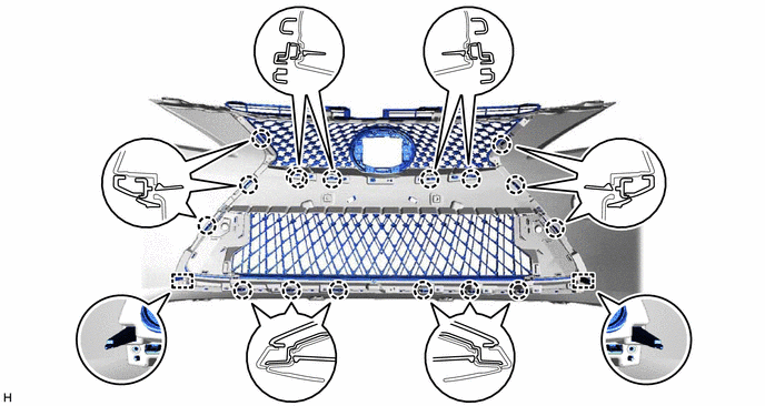
INSTALL RADIATOR GRILLE SUB-ASSEMBLY
-
Insert the guides and attach the claws.
-
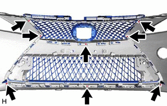
Install the radiator grille assembly with the 8 screws.
-
-
INSTALL NO. 2 MOULDING TAPE
Tech Tips
When installing the No. 2 moulding tape, heat the front bumper cover.
Standard Item Temperature Front Bumper Cover 20 to 30°C (68 to 86°F)
-
Clean the No. 2 moulding tape installation surface with a non-residue solvent.
-
Remove the peeling paper on a new No. 2 moulding tape while making sure not to touch the adhesional surface.
-
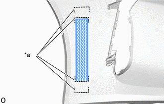
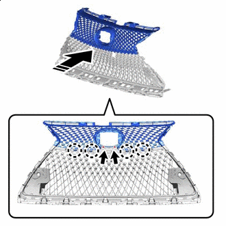
*a Mark-off Line Install the No. 2 moulding tape in the position shown in the illustration.
Note
Press the No. 2 moulding tape firmly to install it.
Tech Tips
Use the same procedure for the RH side and LH side.
-
Remove the application tape.
-
-
INSTALL NO. 1 MOULDING TAPE
Tech Tips
When installing the No. 1 moulding tape, heat the front bumper cover.
Standard Item Temperature Front Bumper Cover 20 to 30°C (68 to 86°F)
-
Clean the No. 1 moulding tape installation surface with a non-residue solvent.
-
Remove the peeling paper on a new No. 1 moulding tape while making sure not to touch the adhesional surface.
-
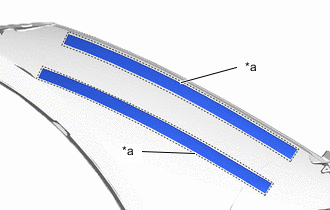
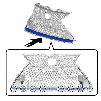
*a Mark-off Line Install the No. 1 moulding tape in the position shown in the illustration.
Note
Press the No. 1 moulding tape firmly to install it.
Tech Tips
Use the same procedure for the RH side and LH side.
-
-
INSTALL NO. 1 FRONT BUMPER SIDE SUPPORT LH
Tech Tips
When installing the No. 1 front bumper side support LH, heat the No. 1 front bumper side support LH.
Standard Item Temperature No. 1 Front Bumper Side Support LH 20 to 30°C (68 to 86°F)
-
Clean the No. 1 front bumper side support LH installation surface with a non-residue solvent.
-
Remove the peeling paper on the No. 1 moulding tape while making sure not to touch the adhesional surface.
-
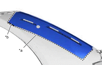
*a Mark-off Line *b Rib Install the No. 1 front bumper side support LH in the position shown in the illustration.
Note
Press the No. 1 front bumper side support LH firmly to install it.
Tech Tips
Install the No. 1 front bumper side support LH while it is pressed against the rib.
-
-
INSTALL NO. 1 FRONT BUMPER SIDE SUPPORT RH
Tech Tips
Use the same procedure described for the LH side.
-
INSTALL FRONT FENDER LINER RETAINER
-
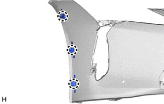
Attach the claw to install the 3 front fender liner retainers.
-
-
INSTALL FRONT BUMPER HOLE COVER LH
-
Install in this Direction Install the anti-drop hook.
-
Attach the claws and install the front bumper hole cover LH.
-
-
INSTALL NO. 2 WASHER BRACKET
-
INSTALL WASHER BRACKET
Tech Tips
Use the same procedure described for the LH side.
-
INSTALL HEADLIGHT WASHER ACTUATOR SUB-ASSEMBLY LH
-
INSTALL HEADLIGHT WASHER ACTUATOR SUB-ASSEMBLY RH
Tech Tips
Use the same procedure described for the LH side.
-
INSTALL HEADLIGHT WASHER COVER
-
INSTALL FRONT BUMPER GARNISH LH
-
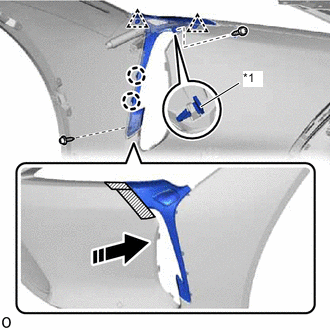
*1 Front Bumper Side Retainer Install in this Direction 
Protective Tape Apply protective tape around the front bumper garnish LH.
-
Attach the clips and claws to install the front bumper side retainer.
-
Install the front bumper garnish LH with the 2 screws.
-
Remove the protective tape.
-
-
INSTALL FRONT BUMPER GARNISH
Tech Tips
Use the same procedure described for the LH side.
-
INSTALL LOWER SIDE RADIATOR GRILLE LH
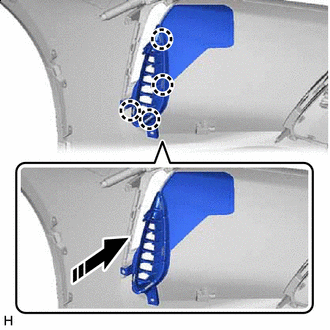
Install in this Direction
-
Attach the claws to install the lower side radiator grille LH as shown in the illustration.
-
-
INSTALL LOWER SIDE RADIATOR GRILLE RH
Tech Tips
Use the same procedure described for the LH side.
-
INSTALL FRONT TURN SIGNAL LIGHT ASSEMBLY LH
-
INSTALL FRONT TURN SIGNAL LIGHT ASSEMBLY RH
Tech Tips
Use the same procedure described for the LH side.
-
INSTALL ULTRASONIC SENSOR CLIP
-
INSTALL FRONT CENTER ULTRASONIC SENSOR
-
INSTALL FRONT CORNER ULTRASONIC SENSOR RETAINER
-
INSTALL FRONT CORNER ULTRASONIC SENSOR
-
INSTALL NO. 4 ENGINE ROOM WIRE
-
INSTALL FRONT BUMPER EXTENSION MOUNTING BRACKET
-
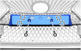
for Type A:
-
Attach the claws to install the front bumper extension mounting bracket.
-
Install the 2 screws.
-
-
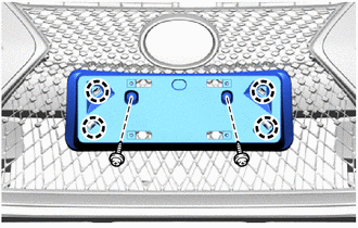
for Type B:
-
Attach the claws to install the front bumper extension mounting bracket.
-
Install the 2 screws.
-
-
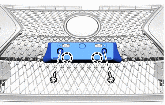
for Type C:
-
Attach the claws to install the front bumper extension mounting bracket.
-
Install the 2 screws.
-
-
-
INSTALL RADIATOR GRILLE (OR FRONT PANEL) EMBLEM
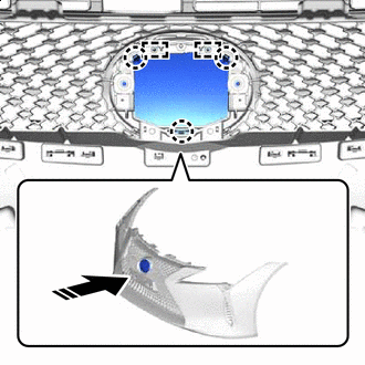
Install in this Direction
-
Attach the guides and claws.
-
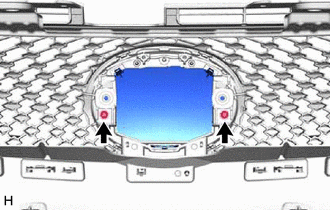
Install the radiator grille (or front panel) emblem with the 2 screws.
-
-
INSTALL MILLIMETER WAVE RADAR SENSOR ASSEMBLY (w/ Dynamic Radar Cruise Control System)
-
INSTALL FRONT BUMPER MOUNTING BRACKET
Install in this Direction
-
Install the front bumper mounting bracket with the 2 clips.
-