LIGHTING SYSTEM Headlight Beam Level Control Actuator Circuit
DESCRIPTION
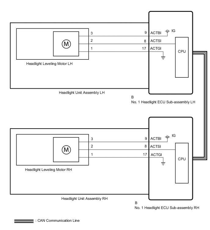
The No. 1 headlight ECU sub-assembly controls the headlight leveling motors.
WIRING DIAGRAM
CAUTION / NOTICE / HINT
Note
If the No. 1 headlight ECU sub-assembly LH has been replaced, it is necessary to synchronize the vehicle information.
PROCEDURE
-
PERFORM ACTIVE TEST USING GTS
-
Perform the Active Test according to the display on the GTS.
Body Electrical > HL AutoLeveling > Active TestTester Display Measurement Item Control Range Diagnostic Note Drive The Leveling Motor Headlight leveling motor OFF or ON Perform the Active Test with the power switch on (READY) and vehicle stopped.
Body Electrical > HL AutoLeveling > Active TestTester Display Drive The Leveling Motor OK Headlight leveling motors operate normally. Result Result Proceed to OK A NG (for LH Side) B NG (for RH Side) C
A 
PROCEED TO NEXT SUSPECTED AREA SHOWN IN PROBLEM SYMPTOMS TABLE Click here
C 
CHECK HEADLIGHT UNIT ASSEMBLY RH Click here
B 
-
-
CHECK HEADLIGHT UNIT ASSEMBLY LH
-
Interchange the headlight unit assembly LH with RH and connect the connectors to them.
-
Check that the headlight leveling motor LH operate normally.
OK Headlight leveling motor LH operate normally. Result Proceed to OK NG
NG
REPLACE NO. 1 HEADLIGHT ECU SUB-ASSEMBLY LH Click here
OK
-
-
CHECK HEADLIGHT UNIT ASSEMBLY LH
-
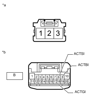
*a Component without harness connected
(Headlight Leveling Motor LH)
*b Component without harness connected
(Headlight ECU Sub-assembly LH)
Remove the headlight leveling motor LH.
-
Remove the headlight ECU sub-assembly LH.
-
Measure the resistance according to the value(s) in the table below.
Standard Resistance Tester Connection Condition Specified Condition 3 - B-9 (ACTBI) Always Below 1 Ω 2 - B-8 (ACTSI) Always Below 1 Ω 1 - B-17 (ACTGI) Always Below 1 Ω Result Proceed to OK NG
OK
REPLACE HEADLIGHT LEVELING MOTOR LH Click here
NG
REPLACE HEADLIGHT UNIT ASSEMBLY LH Click here
-
-
CHECK HEADLIGHT UNIT ASSEMBLY RH
-
Interchange the headlight unit assembly RH with LH and connect the connectors to them.
-
Check that the headlight leveling motor RH operate normally.
OK Headlight leveling motor RH operate normally. Result Proceed to OK NG
NG
REPLACE NO. 1 HEADLIGHT ECU SUB-ASSEMBLY RH Click here
OK
-
-
CHECK HEADLIGHT UNIT ASSEMBLY RH
-
*a Component without harness connected
(Headlight Leveling Motor RH)
*b Component without harness connected
(Headlight ECU Sub-assembly RH)
Remove the headlight leveling motor RH.
-
Remove the headlight ECU sub-assembly RH.
-
Measure the resistance according to the value(s) in the table below.
Standard Resistance Tester Connection Condition Specified Condition 3 - B-9 (ACTBI) Always Below 1 Ω 2 - B-8 (ACTSI) Always Below 1 Ω 1 - B-17 (ACTGI) Always Below 1 Ω Result Proceed to OK NG
OK
REPLACE HEADLIGHT LEVELING MOTOR RH Click here
NG
REPLACE HEADLIGHT UNIT ASSEMBLY RH Click here
-