HEADLIGHT DIMMER SWITCH INSPECTION
PROCEDURE
-
INSPECT TURN SIGNAL SWITCH (for Headlight Dimmer Switch LH Side Type)
-
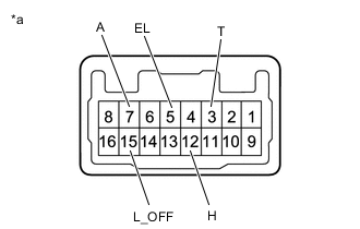
Inspect the light control switch.
-
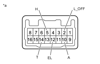
*a Component without harness connected
(Turn Signal Switch)
Measure the resistance according to the value(s) in the table below.
Standard Resistance If the result is not as specified, replace the turn signal switch.Tester Connection Switch Condition Specified Condition 2 (L_OFF) - 12 (EL) Light control switch OFF Below 1 Ω 10 (A) - 12 (EL) Light control switch AUTO position 14 (T) - 12 (EL) Light control switch TAIL position 5 (H) - 12 (EL) Light control switch HEAD position
-
-
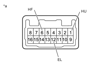
*a Component without harness connected
(Turn Signal Switch)
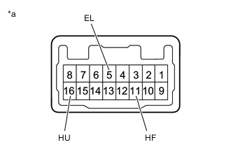
Inspect the headlight dimmer switch.
-
Measure the resistance according to the value(s) in the table below.
Standard Resistance If the result is not as specified, replace the turn signal switch.Tester Connection Switch Condition Specified Condition 6 (HF) - 12 (EL) Headlight dimmer switch flash position Below 1 Ω 1 (HU) - 12 (EL) Headlight dimmer switch high position Below 1 Ω
-
-
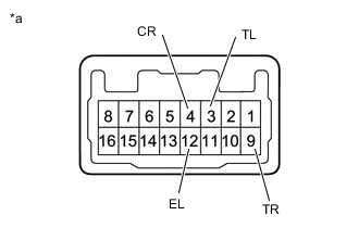
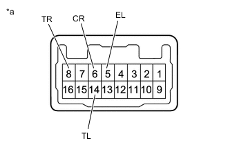
*a Component without harness connected
(Turn Signal Switch)
Inspect the turn signal light switch.
-
Measure the resistance according to the value(s) in the table below.
Standard Resistance If the result is not as specified, replace the turn signal switch.Tester Connection Switch Condition Specified Condition 9 (TR) - 12 (EL) Turn signal switch neutral position 10 kΩ or higher 3 (TL) - 12 (EL) 9 (TR) - 12 (EL) Turn signal switch right turn position
(self cancel condition)
Below 1 Ω 9 (TR) - 12 (EL) Turn signal switch right turn position
(cancel ratchet operation condition)
Below 1 Ω 9 (TR) - 4 (CR) 4 (CR) - 12 (EL) 3 (TL) - 12 (EL) Turn signal switch left turn position
(self cancel condition)
Below 1 Ω 3 (TL) - 12 (EL) Turn signal switch left turn position
(cancel ratchet operation condition)
Below 1 Ω 3 (TL) - 4 (CR) 4 (CR) - 12 (EL)
Tech Tips
-
The self cancel condition indicates when the turn signal switch returns to the neutral position after releasing your hand from the switch (switch is operated within 6.3°).
-
The cancel ratchet operation condition indicates the condition when the turn signal switch does not return to the neutral position even after releasing your hand (switch operation is 10.5°).
-
-
-
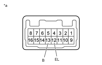
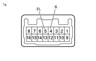
*a Component without harness connected
(Turn Signal Switch)
Inspect the rear fog light switch.
-
Measure the resistance according to the value(s) in the table below.
Standard Resistance If the result is not as specified, replace the turn signal switch.Tester Connection Switch Condition Specified Condition 13 (B) - 12 (EL) Rear fog light switch off 10 kΩ or higher Rear fog light switch on Below 1 Ω
-
-
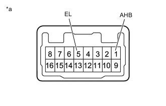
*a Component without harness connected
(Turn Signal Switch)
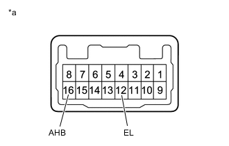
Inspect the AHB switch.
-
Measure the resistance according to the value(s) in the table below.
Standard Resistance If the result is not as specified, replace the turn signal switch.Tester Connection Switch Condition Specified Condition 16 (AHB) - 12 (EL) AHB switch off 10 kΩ or higher AHB switch on Below 1 Ω
-
-
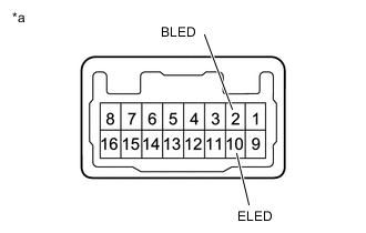
*a Component without harness connected
(Turn Signal Switch)
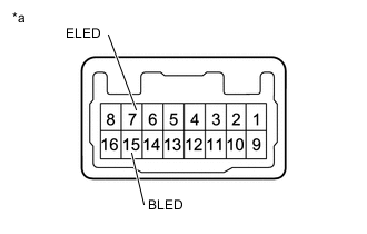
Check the illumination.
-
Apply auxiliary battery voltage to the connector and check the illumination conditions.
OK If the result is not as specified, replace the turn signal switch.Auxiliary Battery Connection Specified Condition Positive (+) → 15 (BLED)
Negative (-) → 7 (ELED)
AHB indicator illuminates
-
-
-
INSTALL TURN SIGNAL SWITCH (for Headlight Dimmer Switch RH Side Type)
-
Inspect the light control switch.
-
*a Component without harness connected
(Turn Signal Switch)
Measure the resistance according to the value(s) in the table below.
Standard Resistance If the result is not as specified, replace the turn signal switch.Tester Connection Switch Condition Specified Condition 15(L_OFF) - 5(EL) Light control switch OFF Below 1 Ω 7(A) - 5(EL) Light control switch AUTO position 3(T) - 5(EL) Light control switch TAIL position 12(H) - 5(EL) Light control switch HEAD position
-
-
Inspect the headlight dimmer switch.
-
*a Component without harness connected
(Turn Signal Switch)
Measure the resistance according to the value(s) in the table below.
Standard Resistance If the result is not as specified, replace the turn signal switch.Tester Connection Switch Condition Specified Condition 11(HF) - 5(EL) Headlight dimmer switch flash position Below 1 Ω 16(HU) - 5(EL) Headlight dimmer switch high position
-
-
Inspect the turn signal light switch.
-
*a Component without harness connected
(Turn Signal Switch)
Measure the resistance according to the value(s) in the table below.
Standard Resistance If the result is not as specified, replace the turn signal switch.Tester Connection Switch Condition Specified Condition 8(TR) - 5(EL) Turn signal switch neutral position 10 kΩ or higher 14(TL) - 5(EL) 8(TR) - 5(EL) Turn signal switch right turn position
(self cancel condition)
Below 1 Ω 8(TR) - 5(EL) Turn signal switch right turn position
(cancel ratchet operation condition)
8(TR) - 6(CR) 6(CR) - 5(EL) 14(TL) - 5(EL) Turn signal switch left turn position
(self cancel condition)
14(TL) - 5(EL) Turn signal switch left turn position
(cancel ratchet operation condition)
14(TL) - 6(CR) 6(CR) - 5(EL)
Tech Tips
-
The self cancel condition indicates when the turn signal switch returns to the neutral position after releasing your hand from the switch (switch is operated within 6.3°).
-
The cancel ratchet operation condition indicates the condition when the turn signal switch does not return to the neutral position even after releasing your hand (switch operation is 10.5°).
-
-
-
Inspect the rear fog light switch.
-
*a Component without harness connected
(Turn Signal Switch)
Measure the resistance according to the value(s) in the table below.
Standard Resistance If the result is not as specified, replace the turn signal switch.Tester Connection Switch Condition Specified Condition 4(B) - 5(EL) Rear fog light switch off 10 kΩ or higher Rear fog light switch on Below 1 Ω
-
-
Inspect the AHB switch.
-
*a Component without harness connected
(Turn Signal Switch)
Measure the resistance according to the value(s) in the table below.
Standard Resistance If the result is not as specified, replace the turn signal switch.Tester Connection Switch Condition Specified Condition 1(AHB) - 5(EL) AHB switch off 10 kΩ or higher AHB switch on Below 1 Ω
-
-
Check the illumination.
-
*a Component without harness connected
(Turn Signal Switch)
Apply auxiliary battery voltage to the connector and check the illumination conditions.
OK If the result is not as specified, replace the turn signal switch.Auxiliary Battery Connection Specified Condition Positive (+) → 2(BLED)
Negative (-) → 10(ELED)
AHB indicator illuminates
-
-