LIGHTING SYSTEM TERMINALS OF ECU
-
CHECK DRIVER SIDE JUNCTION BLOCK ASSEMBLY AND MAIN BODY ECU (MULTIPLEX NETWORK BODY ECU)
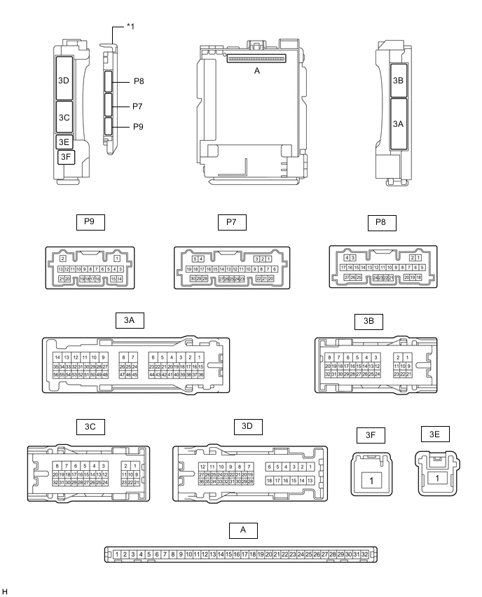
*1 Main Body ECU (Multiplex Network Body ECU) - -
-
Remove the main body ECU (multiplex network body ECU) from the driver side junction block assembly.
-
Connect the driver side junction block assembly connectors.
-
Measure the voltage and resistance according to the value(s) in the table below.
Terminal No. (Symbol) Wiring Color Terminal Description Condition Specified Condition A-32 (IG) - Body ground Note - Body ground Ignition power supply Power switch on (IG) 11 to 14 V Power switch off Below 1 V A-31 (BECU) - Body ground Note - Body ground Auxiliary battery power supply Power switch off 11 to 14 V A-30 (ACC) - Body ground Note - Body ground ACC power supply Power switch on (ACC) 11 to 14 V Power switch off Below 1 V A-11 (GND1) - Body ground Note - Body ground Ground Always Below 1 Ω -
Install the main body ECU (multiplex network body ECU).
-
Measure the voltage and pulse according to the value(s) in the table below.
Terminal No. (Symbol) Wiring Color Terminal Description Condition Specified Condition P7-12 (HRY2) - Body ground R - Body ground No. 1 headlight ECU sub-assembly LH power supply Power switch on (IG) Below 1.5 V Power switch off 6 V or higher 3C-19 (HRLY) - Body ground*1 V - Body ground No. 1 headlight ECU sub-assembly RH power supply Power switch on (IG) Below 1.5 V Power switch off 6 V or higher 3C-20 (HRLY) - Body ground*2 V - Body ground No. 1 headlight ECU sub-assembly RH power supply Power switch on (IG) Below 1.5 V Power switch off 6 V or higher P7-23 (CLTB) - P7-25 (CLTE) V - G Automatic light control sensor power supply output Power switch on (IG) and light control switch in AUTO position 11 to 14 V Power switch off Below 1 V P7-24 (CLTS) - Body ground GR - Body ground Automatic light control sensor signal input Power switch off Below 1 V Power switch on (IG), material which blocks light used to cover and then uncover top of automatic light control sensor Pulse generation
(See waveform 1)
P7-16 (HEAD) - Body ground SB - Body ground Light control switch in HEAD position signal input Light control switch in HEAD position Below 1 V Light control switch not in HEAD position 11 to 14 V P9-2 (MILE) - Body ground BR - Body ground Door outside handle sub-assembly (outside handle lights) signal output Door outside handle sub-assembly (outside handle lights) off Below 1 V Door outside handle sub-assembly (outside handle lights) on 11 to 14 V *1: for LHD
*2: for RHD
-
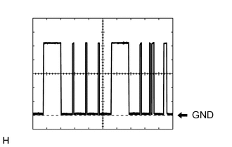
Waveform 1
Item Content Terminal No. (Symbol) P7-24 (CLTS) - Body ground Tool Setting 2 V/DIV., 10 ms./DIV. Condition Power switch on (IG), material which blocks light used to cover and then uncover top of automatic light control sensor Tech Tips
The communication waveform changes according to the surrounding brightness.
-
-
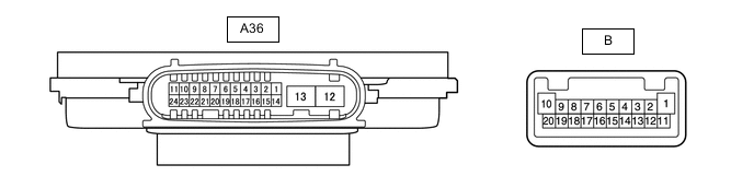
CHECK NO. 1 HEADLIGHT ECU SUB-ASSEMBLY LH
-
Disconnect the A36 No. 1 headlight ECU sub-assembly LH connector.
-
Measure the resistance and voltage according to the value(s) in the table below.
Terminal No. (Symbol) Wiring Color Terminal Description Condition Specified Condition A36-4 (IG) - Body ground G - Body ground Ignition power supply Power switch off Below 1 V Power switch on (IG) 11 to 14 V A36-13 (ECUB) - Body ground G - Body ground Power supply Approximately 15 seconds elapsed after turning the power switch off Below 1 V Power switch on (IG) or within approximately 15 seconds of power switch being turned off 11 to 14 V A36-12 (GND) - Body ground W-B - Body ground Ground Always Below 1 Ω -
Reconnect the A36 No. 1 headlight ECU sub-assembly LH connector.
Tech Tips
-
Since the A36 No. 1 headlight ECU sub-assembly LH connector is a waterproof type connector, the voltage and pulses cannot be checked directly. The values listed are for reference only.
-
Since the B No. 1 headlight ECU sub-assembly LH connector is connected inside the headlight assembly, the voltage and pulses cannot be checked directly. The values listed are for reference only.
-
-
Measure the voltage and check of pulses according to the value(s) in the table below.
Terminal No. (Symbol) Wiring Color Terminal Description Condition Specified Condition B-1 - B-10 - Clearance lights/daytime running lights power source Clearance light and daytime running light off Below 1 V Clearance light and daytime running light on 11 to 14 V B-1 - B-16 - Clearance lights/daytime running lights control signal output Clearance light and daytime running light off Below 1 V Clearance light and daytime running light on Pulse generation B-2 - B-3 - Low beam headlights/high beam headlights drive output Low beam headlights and high beam headlights off Below 1 V Low beam headlights or high beam headlights on 40 to 48 V B-4 - B-14 - Low beam fan power source Low beam headlights off Below 1 V Low beam headlights on 4.75 to 5.25 V B-15 - B-14 - Low beam fan control signal input Low beam headlights off Below 1 V Low beam headlights on Pulse generation B-5 - B-6* - Cornering light drive output Cornering light off Below 1 V Cornering light on 11 to 14 V B-8 - B-17 - Headlight leveling motor signal output Power switch on (READY), when low beam headlights turn on, vehicle height not changed Below 1 V Power switch on (READY), when low beam headlights turn on, vehicle height changed and maintained for more than 3 seconds 1 to 14 V B-9 - B-17 - Headlight leveling motor power source Power switch off Below 1 V Power switch on (IG) 11 to 14 V B-11 - B-19 - High beam headlights drive output High beam headlights off Below 1 V High beam headlights on 11 to 14 V *: w/ Cornering Light
-
-
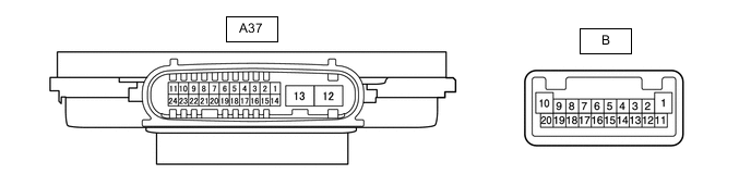
CHECK NO. 1 HEADLIGHT ECU SUB-ASSEMBLY RH
-
Disconnect the A37 No. 1 headlight ECU sub-assembly RH connector.
-
Measure the resistance and voltage according to the value(s) in the table below.
Terminal No. (Symbol) Wiring Color Terminal Description Condition Specified Condition A37-4 (IG) - Body ground R - Body ground Ignition power supply Power switch off Below 1 V Power switch on (IG) 11 to 14 V A37-13 (ECUB) - Body ground R - Body ground Power supply Approximately 15 seconds elapsed after turning the power switch off Below 1 V Power switch on (IG) or within approximately 15 seconds of power switch being turned off 11 to 14 V A37-12 (GND) - Body ground BR - Body ground Ground Always Below 1 Ω -
Reconnect the A37 No. 1 headlight ECU sub-assembly RH connector.
Tech Tips
-
Since the A37 No. 1 headlight ECU sub-assembly RH connector is a waterproof type connector, the voltage and pulses cannot be checked directly. The values listed are for reference only.
-
Since the B No. 1 headlight ECU sub-assembly RH connector is connected inside the headlight assembly, the voltage and pulses cannot be checked directly. The values listed are for reference only.
-
-
Measure the voltage and check of pulses according to the value(s) in the table below.
Terminal No. (Symbol) Wiring Color Terminal Description Condition Specified Condition B-1 - B-10 - Clearance lights/daytime running lights power source Clearance light and daytime running light off Below 1 V Clearance light and daytime running light on 11 to 14 V B-1 - B-16 - Clearance lights/daytime running lights control signal output Clearance light and daytime running light off Below 1 V Clearance light and daytime running light on Pulse generation B-2 - B-3 - Low beam headlights/high beam headlights drive output Low beam headlights and high beam headlights off Below 1 V Low beam headlights or high beam headlights on 40 to 48 V B-4 - B-14 - Low beam fan power source Low beam headlights off Below 1 V Low beam headlights on 4.75 to 5.25 V B-15 - B-14 - Low beam fan control signal input Low beam headlights off Below 1 V Low beam headlights on Pulse generation B-5 - B-6* - Cornering light drive output Cornering light off Below 1 V Cornering light on 11 to 14 V B-8 - B-17 - Headlight leveling motor signal output Power switch on (READY), when low beam headlights turn on, vehicle height not changed Below 1 V Power switch on (READY), when low beam headlights turn on, vehicle height changed and maintained for more than 3 seconds 1 to 14 V B-9 - B-17 - Headlight leveling motor power source Power switch off Below 1 V Power switch on (IG) 11 to 14 V B-11 - B-19 - High beam headlights drive output High beam headlights off Below 1 V High beam headlights on 11 to 14 V *: w/ Cornering Light
-
-
CHECK COMBINATION METER ASSEMBLY
-
CHECK FORWARD RECOGNITION CAMERA
-
CHECK NO. 1 SEMICONDUCTOR POWER INTEGRATION ECU
-
CHECK NO. 3 SEMICONDUCTOR POWER INTEGRATION ECU