FRONT WIPER MOTOR REMOVAL
CAUTION / NOTICE / HINT
Note
The windshield wiper motor does not have a link mechanism. Therefore, make sure that the right and left positions do not deviate when removing and installing the front wiper arm.
Tech Tips
-
Use the same procedure for RHD and LHD vehicles.
-
The procedure listed below is for LHD vehicles.
PROCEDURE
-
REMOVE FRONT WIPER ARM HEAD CAP
-
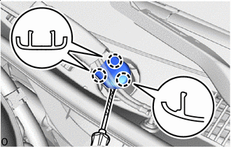

Protective Tape Using a thin-bladed screwdriver with its tip wrapped with protective tape, detach the claws and remove the front wiper arm head cap.
Tech Tips
Use the same procedure for the other side.
-
-
REMOVE WINDSHIELD WIPER ARM AND BLADE ASSEMBLY LH
-
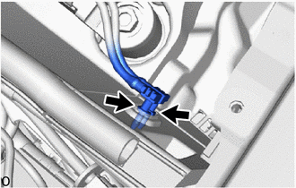
Disconnect the 2 washer hoses.
-
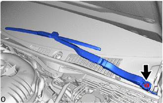
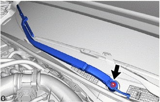
Remove the nut and the windshield wiper arm and blade assembly LH.
Tech Tips
Perform work from directly above so that the windshield wiper arm and blade assembly RH does not rotate when removeing the nut.
-
-
REMOVE WINDSHIELD WIPER ARM AND BLADE ASSEMBLY RH
-
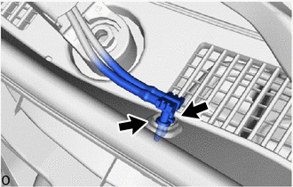
Disconnect the 2 washer hoses.
-
Remove the nut and the windshield wiper arm and blade assembly RH.
Tech Tips
Perform work from directly above so that the windshield wiper arm and blade assembly RH does not rotate when removeing the nut.
-
-
REMOVE RADIATOR SUPPORT TO FRAME SEAL RH
-
REMOVE ENGINE ROOM SIDE COVER LH
-
REMOVE LOWER RADIATOR AIR DEFLECTOR
-
REMOVE FRONT FENDER REINFORCEMENT TOP SUB-ASSEMBLY LH
-
REMOVE FRONT FENDER REINFORCEMENT TOP SUB-ASSEMBLY RH
Tech Tips
Use the same procedure described for the LH side.
-
SEPARATE ROOF DRIP SIDE FINISH MOULDING RH
-
Protective Tape Apply protective tape around the roof drip side finish moulding RH.
-
Using the moulding remover B, detach the claws and separate the roof drip side finish moulding RH.
-
-
SEPARATE ROOF DRIP SIDE FINISH MOULDING LH
Tech Tips
Use the same procedure described for the RH side.
-
REMOVE NO. 2 COWL TOP PANEL INSULATOR (for LHD)
-
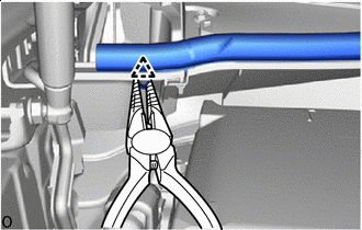
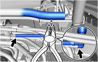
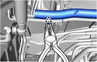
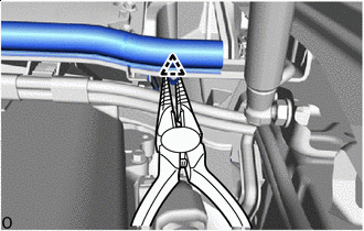
Protective Tape Using needle-nose pliers with their tips wrapped with protective tape, remove the clip of the hood to cowl top seal.
-
Remove the clip.
-
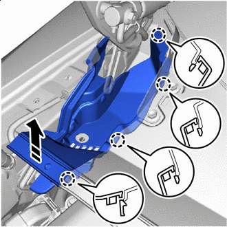

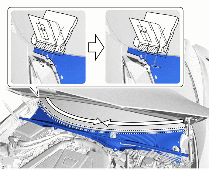
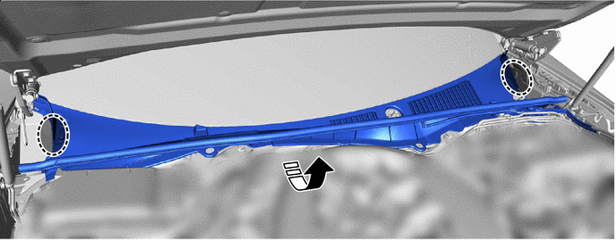
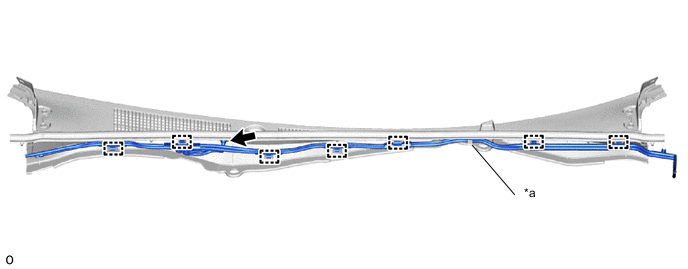
Remove in this Direction Pull in the direction of the arrow shown in the illustration to detach the claws and remove the No. 2 cowl top panel insulator.
-
-
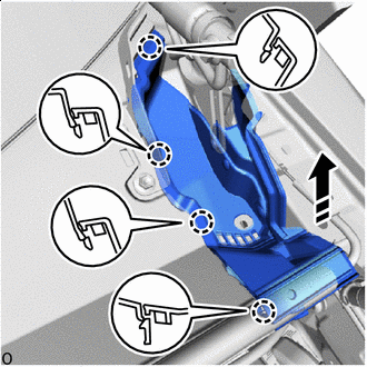
REMOVE NO. 3 COWL TOP PANEL INSULATOR (for LHD)
-
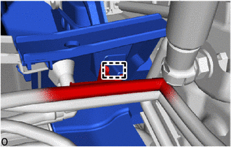
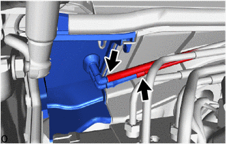
Detach the clamp.
-
Protective Tape Disconnect the washer hoses as shown in the illustration.
-
Using needle-nose pliers with their tips wrapped with protective tape, remove the clip of the hood to cowl top seal.
-
Remove the clip.
-
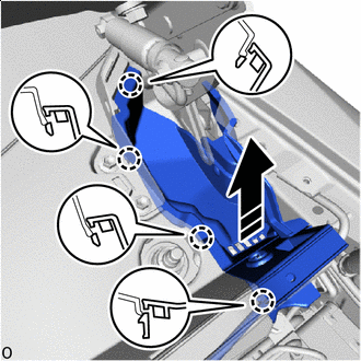
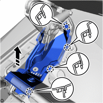
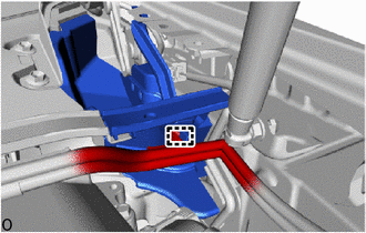
Remove in this Direction Pull in the direction of the arrow shown in the illustration to detach the claws and remove the No. 3 cowl top panel insulator.
-
-
REMOVE NO. 2 COWL TOP PANEL INSULATOR (for RHD)
-
Protective Tape Using needle-nose pliers with their tips wrapped with protective tape, remove the clip of the hood to cowl top seal.
-
Remove the clip.
-
Remove in this Direction Pull in the direction of the arrow shown in the illustration to detach the claws and remove the No. 2 cowl top panel insulator.
-
Disconnect the washer hose as shown in the illustration.
-
-
REMOVE NO. 3 COWL TOP PANEL INSULATOR (for RHD)
-
Protective Tape Disconnect the 2 washer hoses.
-
Using needle-nose pliers with their tips wrapped with protective tape, remove the clip of the hood to cowl top seal.
-
Remove the clip.
-
Detach the clamp.
-
Remove in this Direction Pull in the direction of the arrow shown in the illustration to detach the claws and remove the No. 3 cowl top panel insulator.
-
-
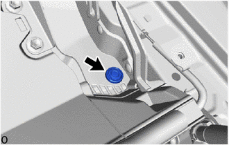
REMOVE WASHER GROMMET
-
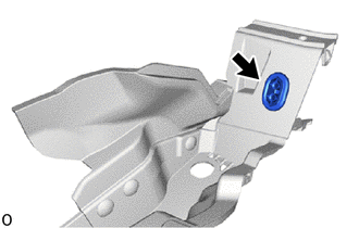
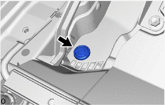
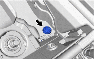
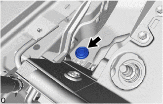
Remove the washer grommet.
Tech Tips
Use the same procedure for the other side.
-
-
REMOVE CENTER COWL TOP VENTILATOR LOUVER
-
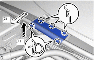
Remove in this Direction (1) 
Remove in this Direction (2) Pull in the direction of the arrow shown in the illustration to detach the claws and remove the center cowl top ventilator louver.
-
-
REMOVE COWL TOP VENTILATOR LOUVER SUB-ASSEMBLY
-
Remove the 2 clips.
-
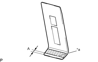
*a Edge of Protective Tape Protective Tape Apply protective tape to a moulding remover as shown in the illustration.
Standard Dimension Area Dimension A 4.0 mm (0.157 in.) -
Insert the moulding remover at the starting position until the edge of the protective tape is aligned with the cowl top ventilator louver sub-assembly as shown in the illustration.
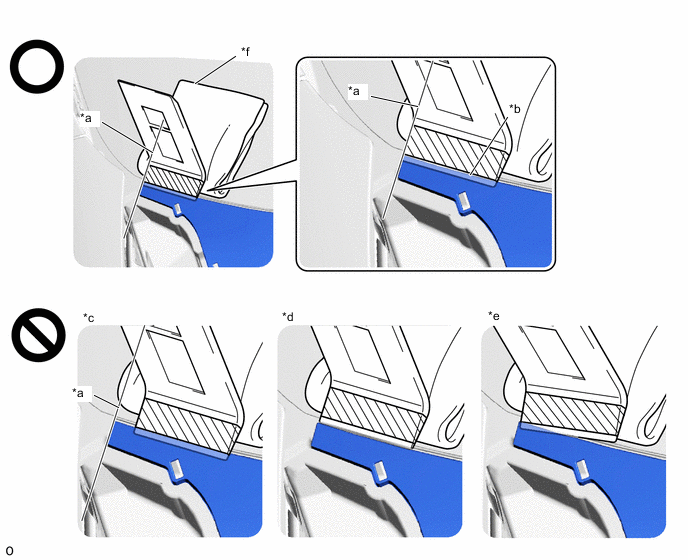
*a Starting Position:
Side of Cowl Top Ventilator Louver Sub-assembly and Moulding Remover Aligned
*b Inserted to Edge of Protective Tape *c Not Inserted at Starting Position *d Not Inserted to Edge of Protective Tape *e Not Inserted Straight *f Piece of Cloth or Equivalent Protective Tape - - Note
-
To prevent damage to the windshield glass, set a piece of cloth between the moulding remover and windshield glass.
-
Make sure to insert the moulding remover until the edge of protective tape is aligned with the cowl top ventilator louver sub-assembly, otherwise the cowl top ventilator louver sub-assembly may be deformed or damaged.
-
-
While pushing the moulding remover in the direction indicated by the arrow (A), push the moulding remover in the direction indicated by the arrow (B) to disengage the cowl top ventilator louver sub-assembly.
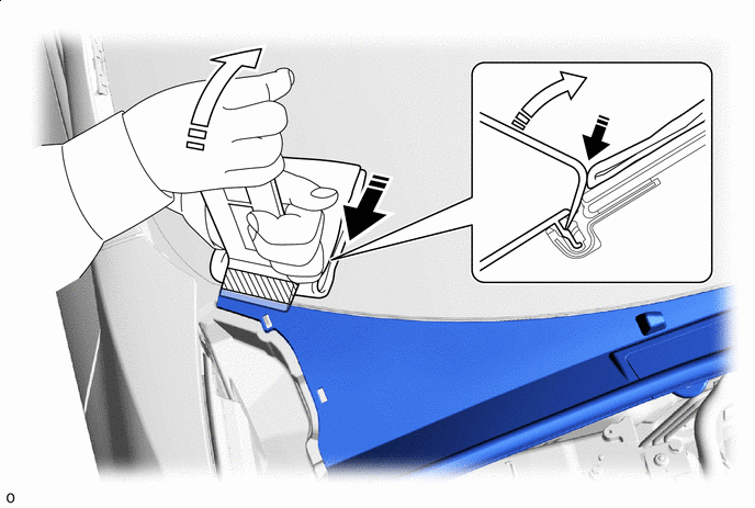
Push in this Direction (A) Push in this Direction (B) Note
-
Make sure to repeat this procedure to disengage the entire cowl top ventilator louver sub-assembly.
-
Make sure to perform this procedure while pushing the moulding remover in the direction indicated by the arrow (A), otherwise the cowl top ventilator louver sub-assembly may be deformed or damaged.
-
Make sure not to pry the cowl top ventilator louver sub-assembly more than necessary to disengage it, otherwise it may be deformed or damaged.
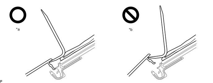
*a Pried Until Disengaged *b Pried Excessively
-
-
Using the moulding remover, repeatedly pry up the cowl top ventilator louver sub-assembly while gradually moving the moulding remover half of its width laterally toward the center of the vehicle and then repeat the procedure from the other side of the vehicle as shown in the illustration to disengage the cowl top ventilator louver sub-assembly from the windshield glass.
*a Half Width of Moulding Remover - - 
Order of Removal - - Note
-
Make sure to move the moulding remover only half of its width laterally after prying up the cowl top ventilator louver sub-assembly, otherwise the cowl top ventilator louver sub-assembly may be damaged or deformed.
-
Make sure not to lift up or pull the cowl top ventilator louver sub-assembly by hand before it is completely disengaged, otherwise it may be deformed or damaged.
-
-
Pull up and turn the front side of the cowl top ventilator louver sub-assembly to remove it.
Remove in this Direction 
Place Hands Here -
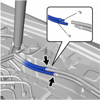
*a Main Nozzle Side *b Sub Nozzle Side Disconnect the 2 washer hoses as shown in the illustration.
Note
Make sure to disconnect the washer hose as shown in the illustration to prevent improper installation during reinstallation.
-
-
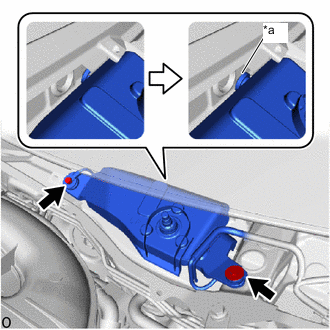
REMOVE WASHER HOSE ASSEMBLY (for LHD)
-
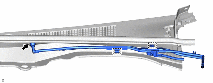
Disconnect the washer hose assembly from the washer grommet.
-
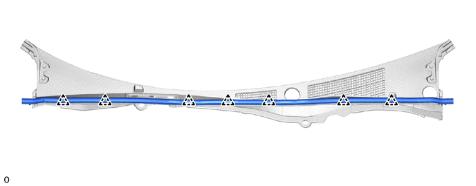
Disconnect the clamps and remove the washer hose assembly.

Grommet - -
-
-
REMOVE WASHER HOSE ASSEMBLY (for RHD)
-
Detach the washer hose assembly from the guide.
-
Disconnect the washer hose assembly from the washer grommet.
-
Disconnect the clamps and remove the washer hose assembly.
*a Guide - - Grommet - -
-
-
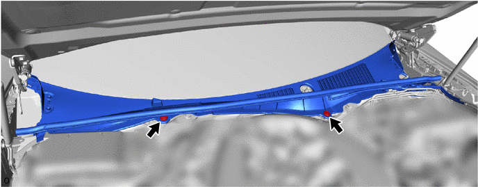
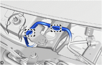
REMOVE HOOD TO COWL TOP SEAL
-
Detach the clips and remove the hood to cowl top seal.
-
-
REMOVE FRONT WIPER MOTOR COVER
-
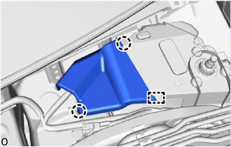
Detach the claws and guide and remove the front wiper motor cover.
-
-
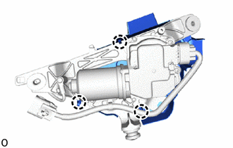
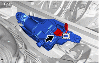
REMOVE FRONT WIPER MOTOR AND BRACKET ASSEMBLY
-
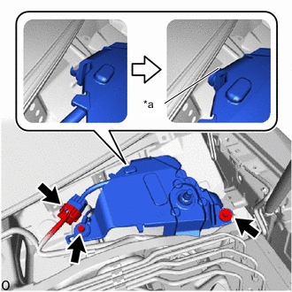
*a Grommet Disconnect the connector.
-
Remove the 2 bolts.
-
Detach the grommet and remove the front wiper motor and bracket assembly as shown in the illustration.
-
-
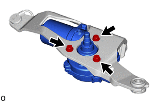
REMOVE NO. 1 WINDSHIELD WIPER SHAFT COVER
-
Detach the claws and remove the No. 1 windshield wiper shaft cover.
-
-
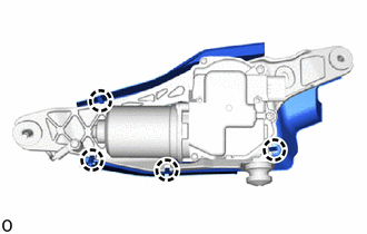
REMOVE WINDSHIELD WIPER MOTOR ASSEMBLY
-
Disconnect the connector and detach the clamp.
-
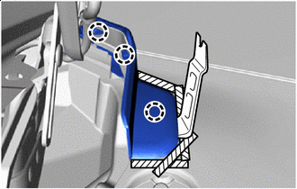
Remove the 3 screws and windshield wiper motor assembly from the wiper bracket assembly.
-
-
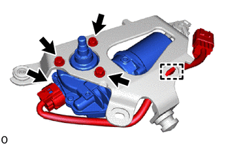
REMOVE NO. 2 FRONT WIPER MOTOR AND BRACKET ASSEMBLY
-
Detach the clamps.
-
*a Grommet Remove the 2 bolts.
-
Detach the grommet and remove the No. 2 front wiper motor and bracket assembly as shown in the illustration.
-
Disconnect the connector and detach the clamp.
-
-
REMOVE NO. 2 WINDSHIELD WIPER SHAFT COVER
-
Detach the claws and remove the No. 2 windshield wiper shaft cover.
-
-
REMOVE NO. 2 WINDSHIELD WIPER MOTOR ASSEMBLY
-
Remove the 3 screws and No. 2 windshield wiper motor assembly from the wiper bracket assembly.
-