LIGHTING SYSTEM, Diagnostic DTC:B242F
| DTC Code | DTC Name |
|---|---|
| B242F | Open in B Power Line |
DESCRIPTION
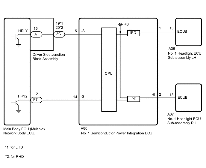
The No. 1 headlight ECU sub-assembly operates using the power source voltage input from the IG terminal and ECUB terminal.
The power source voltage of the ECUB terminal is supplied when the main body ECU (multiplex network body ECU) turns the ECUB power supply relay (No. 1 semiconductor power integration ECU) to ON.
The No. 1 headlight ECU sub-assembly compares the power source voltage supply condition of the IG terminal and ECUB terminal and monitors the result.
| DTC No. | Detection Item | DTC Detection Condition | Trouble Area | DTC Output from |
|---|---|---|---|---|
| B242F | Open in B Power Line |
Detection condition:
Malfunction status:
Malfunction duration: |
|
|
WIRING DIAGRAM
CAUTION / NOTICE / HINT
Note
-
If the No. 1 headlight ECU sub-assembly LH has been replaced, it is necessary to synchronize the vehicle information.
-
Before replacing the main body ECU (multiplex network body ECU), refer to Service Bulletin.
-
First, confirm that there is no malfunction in the power integration system. Refer to the How to Proceed with Troubleshooting procedure.
-
After turning the power switch off, waiting time may be required before disconnecting the cable from the negative (-) auxiliary battery terminal. Therefore, make sure to read the disconnecting the cable from the negative (-) auxiliary battery terminal notices before proceeding with work.
-
When disconnecting the cable from the negative (-) auxiliary battery terminal while performing repairs, some systems need to be initialized after the cable is reconnected.
PROCEDURE
-
CHECK FOR DTC
-
Clear the DTCs.
Body Electrical > HL AutoLeveling > Clear DTCs
Body Electrical > HL AutoLeveling (Sub) > Clear DTCs -
Turn the power switch on (IG) and wait for at least 10 seconds.
-
Check for DTCs.
Body Electrical > HL AutoLeveling > Trouble Codes
Body Electrical > HL AutoLeveling (Sub) > Trouble CodesOK DTC B242F is not output. Result Result Proceed to OK A NG (DTC output from No. 1 headlight ECU sub-assembly LH) B NG (DTC output from No. 1 headlight ECU sub-assembly RH) C
A 
USE SIMULATION METHOD TO CHECK Click here
C 
READ VALUE USING GTS Click here
B 
-
-
READ VALUE USING GTS
-
Turn the power switch on (IG).
-
Using the GTS, read the Data List.
Body Electrical > Power Integration No.1 > Data ListTester Display Measurement Item Range Normal Condition Diagnostic Note Status of Headlight ECU LH Fuse No. 1 headlight ECU sub-assembly LH fuse condition Connect or Disconnect Connect: Fuse not shut off
Disconnect: Fuse shut off
-
Body Electrical > Power Integration No.1 > Data ListTester Display Status of Headlight ECU LH Fuse OK The Data List value displays "Connect". Result Proceed to OK NG
NG
CHECK NO. 1 HEADLIGHT ECU SUB-ASSEMBLY LH Click here
OK
-
-
READ VALUE USING GTS
-
Turn the power switch on (IG).
-
Using the GTS, read the Data List.
Body Electrical > Power Integration No.1 > Data ListTester Display Measurement Item Range Normal Condition Diagnostic Note Headlight ECU LH Input Signal No. 1 headlight ECU sub-assembly LH input OFF or ON OFF: No. 1 headlight ECU sub-assembly LH is not input
ON: No. 1 headlight ECU sub-assembly LH is input
-
Body Electrical > Power Integration No.1 > Data ListTester Display Headlight ECU LH Input Signal OK The Data List value displays "ON". Result Proceed to OK NG
NG
CHECK NO. 1 SEMICONDUCTOR POWER INTEGRATION ECU Click here
OK
-
-
READ VALUE USING GTS
-
Turn the power switch on (IG).
-
Using the GTS, read the Data List.
Body Electrical > Power Integration No.1 > Data ListTester Display Measurement Item Range Normal Condition Diagnostic Note Headlight ECU LH Output Signal No. 1 headlight ECU sub-assembly LH output OFF or ON OFF: No. 1 headlight ECU sub-assembly LH has no power supply
ON: No. 1 headlight ECU sub-assembly LH has power supply
-
Body Electrical > Power Integration No.1 > Data ListTester Display Headlight ECU LH Output Signal OK The Data List value displays "ON". Result Proceed to OK NG
NG
REPLACE NO. 1 SEMICONDUCTOR POWER INTEGRATION ECU Click here
OK
-
-
CHECK HARNESS AND CONNECTOR (NO. 1 HEADLIGHT ECU SUB-ASSEMBLY LH - BATTERY)
-

*a Front view of wire harness connector
(to No. 1 Headlight ECU Sub-assembly LH)
Disconnect the No. 1 headlight ECU sub-assembly LH connector.
-
Measure the voltage according to the value(s) in the table below.
Standard Voltage Tester Connection Switch Condition Specified Condition A36-13 (ECUB) - Body ground Power switch on (IG) 9.5 to 14 V Result Proceed to OK NG
OK
REPLACE NO. 1 HEADLIGHT ECU SUB-ASSEMBLY LH Click here
NG
CHECK HARNESS AND CONNECTOR (NO. 1 HEADLIGHT ECU SUB-ASSEMBLY LH - NO. 1 SEMICONDUCTOR POWER INTEGRATION ECU) Click here
-
-
CHECK NO. 1 HEADLIGHT ECU SUB-ASSEMBLY LH
-
Disconnect the A36 No. 1 headlight ECU sub-assembly LH connector.
-
Turn the power switch off and wait for at least 15 seconds.
-
Turn the power switch on (IG).
-
Using the GTS, read the Data List.
Body Electrical > Power Integration No.1 > Data ListTester Display Measurement Item Range Normal Condition Diagnostic Note Status of Headlight ECU LH Fuse No. 1 headlight ECU sub-assembly LH fuse condition Connect or Disconnect Connect: Fuse not shut off
Disconnect: Fuse shut off
-
Body Electrical > Power Integration No.1 > Data ListTester Display Status of Headlight ECU LH Fuse OK The Data List value displays "Connect". Result Proceed to OK NG
OK
REPLACE NO. 1 HEADLIGHT ECU SUB-ASSEMBLY LH Click here
NG
CHECK HARNESS AND CONNECTOR (NO. 1 HEADLIGHT ECU SUB-ASSEMBLY LH - NO. 1 SEMICONDUCTOR POWER INTEGRATION ECU) Click here
-
-
CHECK NO. 1 SEMICONDUCTOR POWER INTEGRATION ECU
-
*a Front view of wire harness connector
(to Driver Side Junction Block Assembly)
Disconnect the driver side junction block assembly connector.
-
Measure the voltage according to the value(s) in the table below.
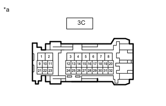
Standard Voltage for LHD Tester Connection Switch Condition Specified Condition 3C-19 - Body ground Power switch off 6 to 14 V for RHD Tester Connection Switch Condition Specified Condition 3C-20 - Body ground Power switch off 6 to 14 V Result Proceed to OK NG
NG
CHECK HARNESS AND CONNECTOR (DRIVER SIDE JUNCTION BLOCK ASSEMBLY - NO. 1 SEMICONDUCTOR POWER INTEGRATION ECU) Click here
OK
-
-
CHECK DRIVER SIDE JUNCTION BLOCK ASSEMBLY
-
Remove the driver side junction block assembly.
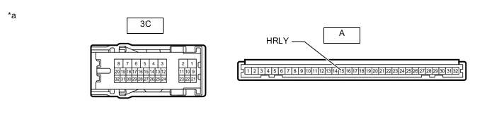
*a Component without harness connected
(Driver Side Junction Block Assembly)
- - -
Remove the main body ECU (multiplex network body ECU) from the driver side junction block assembly.
-
Measure the resistance according to the value(s) in the table below.
Standard Resistance for LHD Tester Connection Condition Specified Condition 3C-19 - A-15 (HRLY) Always Below 1 Ω for RHD Tester Connection Condition Specified Condition 3C-20 - A-15 (HRLY) Always Below 1 Ω Result Proceed to OK NG
OK
REPLACE MAIN BODY ECU (MULTIPLEX NETWORK BODY ECU) Click here
NG
REPLACE DRIVER SIDE JUNCTION BLOCK ASSEMBLY Click here
-
-
CHECK HARNESS AND CONNECTOR (NO. 1 HEADLIGHT ECU SUB-ASSEMBLY LH - NO. 1 SEMICONDUCTOR POWER INTEGRATION ECU)
-
Disconnect the A36 No. 1 headlight ECU sub-assembly LH connector.
-
Disconnect the cable from the negative (-) auxiliary battery terminal.
-
Disconnect the A80 No. 1 semiconductor power integration ECU connector.
-
Measure the resistance according to the value(s) in the table below.
Standard Resistance Tester Connection Condition Specified Condition A80-1 (L) - A36-13 (ECUB) Always Below 1 Ω Result Proceed to OK NG
OK
REPLACE NO. 1 SEMICONDUCTOR POWER INTEGRATION ECU Click here
NG
REPAIR OR REPLACE HARNESS OR CONNECTOR
-
-
CHECK HARNESS AND CONNECTOR (NO. 1 HEADLIGHT ECU SUB-ASSEMBLY LH - NO. 1 SEMICONDUCTOR POWER INTEGRATION ECU)
-
Disconnect the A36 No. 1 headlight ECU sub-assembly LH connector.
-
Disconnect the cable from the negative (-) auxiliary battery terminal.
-
Disconnect the A80 No. 1 semiconductor power integration ECU connector.
-
Measure the resistance according to the value(s) in the table below.
Standard Resistance Tester Connection Condition Specified Condition A80-1 (L) or A36-13 (ECUB) - Body ground Always 10 kΩ or higher Result Proceed to OK NG
OK
REPLACE NO. 1 SEMICONDUCTOR POWER INTEGRATION ECU Click here
NG
REPAIR OR REPLACE HARNESS OR CONNECTOR
-
-
CHECK HARNESS AND CONNECTOR (DRIVER SIDE JUNCTION BLOCK ASSEMBLY - NO. 1 SEMICONDUCTOR POWER INTEGRATION ECU)
-
Disconnect the 3C driver side junction block assembly connector.
-
Disconnect the cable from the negative (-) auxiliary battery terminal.
-
Disconnect the A80 No. 1 semiconductor power integration ECU connector.
-
Measure the resistance according to the value(s) in the table below.
Standard Resistance for LHD Tester Connection Condition Specified Condition 3C-19 - A80-15 (-S) Always Below 1 Ω for RHD Tester Connection Condition Specified Condition 3C-20 - A80-15 (-S) Always Below 1 Ω Result Proceed to OK NG
OK
REPLACE NO. 1 SEMICONDUCTOR POWER INTEGRATION ECU Click here
NG
REPAIR OR REPLACE HARNESS OR CONNECTOR
-
-
READ VALUE USING GTS
-
Turn the power switch on (IG).
-
Using the GTS, read the Data List.
Body Electrical > Power Integration No.1 > Data ListTester Display Measurement Item Range Normal Condition Diagnostic Note Status of Headlight ECU RH Fuse No. 1 headlight ECU sub-assembly RH fuse condition Connect or Disconnect Connect: Fuse not shut off
Disconnect: Fuse shut off
-
Body Electrical > Power Integration No.1 > Data ListTester Display Status of Headlight ECU RH Fuse OK The Data List value displays "Connect". Result Proceed to OK NG
NG
CHECK NO. 1 HEADLIGHT ECU SUB-ASSEMBLY RH Click here
OK
-
-
READ VALUE USING GTS
-
Turn the power switch on (IG).
-
Using the GTS, read the Data List.
Body Electrical > Power Integration No.1 > Data ListTester Display Measurement Item Range Normal Condition Diagnostic Note Headlight ECU RH Input Signal No. 1 headlight ECU sub-assembly RH input OFF or ON OFF: No. 1 headlight ECU sub-assembly RH is not input
ON: No. 1 headlight ECU sub-assembly RH is input
-
Body Electrical > Power Integration No.1 > Data ListTester Display Headlight ECU RH Input Signal OK The Data List value displays "ON". Result Proceed to OK NG
NG
CHECK NO. 1 SEMICONDUCTOR POWER INTEGRATION ECU Click here
OK
-
-
READ VALUE USING GTS
-
Turn the power switch on (IG).
-
Using the GTS, read the Data List.
Body Electrical > Power Integration No.1 > Data ListTester Display Measurement Item Range Normal Condition Diagnostic Note Headlight ECU RH Output Signal No. 1 headlight ECU sub-assembly RH output OFF or ON OFF: No. 1 headlight ECU sub-assembly RH has no power supply
ON: No. 1 headlight ECU sub-assembly RH has power supply
-
Body Electrical > Power Integration No.1 > Data ListTester Display Headlight ECU RH Output Signal OK The Data List value displays "ON". Result Proceed to OK NG
NG
REPLACE NO. 1 SEMICONDUCTOR POWER INTEGRATION ECU Click here REPLACE NO. 1 SEMICONDUCTOR POWER INTEGRATION ECU Click here
OK
-
-
CHECK HARNESS AND CONNECTOR (NO. 1 HEADLIGHT ECU SUB-ASSEMBLY RH - BATTERY)
-
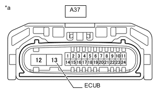
*a Front view of wire harness connector
(to No. 1 Headlight ECU Sub-assembly RH)
Disconnect the No. 1 headlight ECU sub-assembly RH connector.
-
Measure the voltage according to the value(s) in the table below.
Standard Voltage Tester Connection Switch Condition Specified Condition A37-13 (ECUB) - Body ground Power switch on (IG) 9.5 to 14 V Result Proceed to OK NG
OK
REPLACE NO. 1 HEADLIGHT ECU SUB-ASSEMBLY RH Click here
NG
CHECK HARNESS AND CONNECTOR (NO. 1 HEADLIGHT ECU SUB-ASSEMBLY RH - NO. 1 SEMICONDUCTOR POWER INTEGRATION ECU) Click here
-
-
CHECK NO. 1 HEADLIGHT ECU SUB-ASSEMBLY RH
-
Disconnect the A37 No. 1 headlight ECU sub-assembly RH connector.
-
Turn the power switch off and wait for at least 15 seconds.
-
Turn the power switch on (IG).
-
Using the GTS, read the Data List.
Body Electrical > Power Integration No.1 > Data ListTester Display Measurement Item Range Normal Condition Diagnostic Note Status of Headlight ECU RH Fuse No. 1 headlight ECU sub-assembly RH fuse condition Connect or Disconnect Connect: Fuse not shut off
Disconnect: Fuse shut off
-
Body Electrical > Power Integration No.1 > Data ListTester Display Status of Headlight ECU RH Fuse OK The Data List value displays "Connect". Result Proceed to OK NG
OK
REPLACE NO. 1 HEADLIGHT ECU SUB-ASSEMBLY RH Click here
NG
CHECK HARNESS AND CONNECTOR (NO. 1 HEADLIGHT ECU SUB-ASSEMBLY RH - NO. 1 SEMICONDUCTOR POWER INTEGRATION ECU) Click here
-
-
CHECK NO. 1 SEMICONDUCTOR POWER INTEGRATION ECU
-
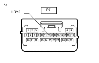
*a Front view of wire harness connector
(to Main Body ECU [Multiplex Network Body ECU])
Disconnect the main body ECU (multiplex network body ECU) connector.
-
Measure the voltage according to the value(s) in the table below.
Standard Voltage Tester Connection Switch Condition Specified Condition P7-12 (HRY2) - Body ground Power switch off 6 to 14 V Result Proceed to OK NG
OK
REPLACE MAIN BODY ECU (MULTIPLEX NETWORK BODY ECU) Click here REPLACE MAIN BODY ECU (MULTIPLEX NETWORK BODY ECU) Click here
NG
CHECK HARNESS AND CONNECTOR (MAIN BODY ECU [MULTIPLEX NETWORK BODY ECU] - NO. 1 SEMICONDUCTOR POWER INTEGRATION ECU) Click here
-
-
CHECK HARNESS AND CONNECTOR (NO. 1 HEADLIGHT ECU SUB-ASSEMBLY RH - NO. 1 SEMICONDUCTOR POWER INTEGRATION ECU)
-
Disconnect the A37 No. 1 headlight ECU sub-assembly RH connector.
-
Disconnect the cable from the negative (-) auxiliary battery terminal.
-
Disconnect the A80 No. 1 semiconductor power integration ECU connector.
-
Measure the resistance according to the value(s) in the table below.
Standard Resistance Tester Connection Condition Specified Condition A80-2 (HI) - A37-13 (ECUB) Always Below 1 Ω Result Proceed to OK NG
OK
REPLACE NO. 1 SEMICONDUCTOR POWER INTEGRATION ECU Click here
NG
REPAIR OR REPLACE HARNESS OR CONNECTOR
-
-
CHECK HARNESS AND CONNECTOR (NO. 1 HEADLIGHT ECU SUB-ASSEMBLY RH - NO. 1 SEMICONDUCTOR POWER INTEGRATION ECU)
-
Disconnect the A37 No. 1 headlight ECU sub-assembly RH connector.
-
Disconnect the cable from the negative (-) auxiliary battery terminal.
-
Disconnect the A80 No. 1 semiconductor power integration ECU connector.
-
Measure the resistance according to the value(s) in the table below.
Standard Resistance Tester Connection Condition Specified Condition A80-2 (HI) or A37-13 (ECUB) - Body ground Always 10 kΩ or higher Result Proceed to OK NG
OK
REPLACE NO. 1 SEMICONDUCTOR POWER INTEGRATION ECU Click here
NG
REPAIR OR REPLACE HARNESS OR CONNECTOR
-
-
CHECK HARNESS AND CONNECTOR (MAIN BODY ECU [MULTIPLEX NETWORK BODY ECU] - NO. 1 SEMICONDUCTOR POWER INTEGRATION ECU)
-
Disconnect the P7 main body ECU (multiplex network body ECU) connector.
-
Disconnect the cable from the negative (-) auxiliary battery terminal.
-
Disconnect the A80 No. 1 semiconductor power integration ECU connector.
-
Measure the resistance according to the value(s) in the table below.
Standard Resistance Tester Connection Condition Specified Condition P7-12 (HRY2) - A80-14 (-S) Always Below 1 Ω Result Proceed to OK NG
OK
REPLACE NO. 1 SEMICONDUCTOR POWER INTEGRATION ECU Click here
NG
REPAIR OR REPLACE HARNESS OR CONNECTOR
-