FUEL LID LOCK CONTROL CABLE ASSEMBLY INSPECTION
PROCEDURE
-
INSPECT FUEL LID WITH MOTOR LOCK ASSEMBLY
-
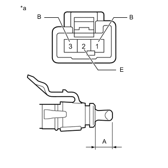
*a Component without harness connected
(Fuel Lid with Motor Lock Assembly)
Check the operation of the fuel lid with motor lock assembly.
-
Apply auxiliary battery voltage to the fuel lid with motor lock assembly connector, and check that the fuel lid with motor lock assembly operates smoothly as follows.
OK Auxiliary battery Connection Specified Condition Auxiliary battery positive (+) → Terminal 1 (B)
Auxiliary battery negative (-) → Terminal 2 (E)
Shaft retracted
(Lid Open)
If the result is not as specified, replace the fuel lid with motor lock assembly.
-
-
Measure the shaft stroke.
Standard Area Specified Condition A 17.1 to 18.3 mm (0.673 to 0.720 in.) If the result is not as specified, replace the fuel lid with motor lock assembly.
-
Check the resistance. (w/ Canister Pump Module)
-
Measure the resistance according to the value(s) in the table below.
Standard Resistance Tester Connection Condition Specified Condition Terminal 2 (E) - Terminal 3 (B) Not Push the Shaft
(Lid Open)
Below 1 Ω Push the Shaft
(Lid Close)
10 kΩ or higher If the result is not as specified, replace the fuel lid with motor lock assembly.
-
-